Guide plate for a system for fastening a rail to a substrate, and a system comprising a guide plate of this type

a technology of guide plate and substrate, which is applied in the direction of track superstructure, roads, constructions, etc., can solve the problems of clip deformation, greatly reduced spring force, and loss of the spring properties required for properly holding down the rail

Active Publication Date: 2010-08-12
VOSSLOH WERKE GMBH
View PDF7 Cites 19 Cited by
  • Summary
  • Abstract
  • Description
  • Claims
  • Application Information

AI Technical Summary

Benefits of technology

[0014]Against this background, the object of the invention was to provide a component allowing the requirements of modern rail travel operation to be met even in fastening systems of the type in which the forces occurring during travel operation are dissipated via a shoulder present on or in the fixed substrate.

Problems solved by technology

In practice, it has been found that, under the high loads resulting from heavy-load or high-speed traffic, force and spring excursion losses, as a result of which the spring force is greatly reduced, occur in the spring clips used in these systems within a short period of use.
It can also occur that the spring clips are deformed during installation to the extent that they lose the spring properties required for properly holding down the rail.
A further disadvantage of the known the Safelok system, which has a particularly negative effect specifically in high-speed and heavy-load traffic, consists in the fact that in this system the rail is not protected against tilting which can occur, in particular, when high transverse forces occur.
Finally, in the known Safelok system, the requirement for maximum possible insulation of the rail in relation to the substrate supporting it may be fulfilled only in a highly complex manner.

Method used


Image

  • Guide plate for a system for fastening a rail to a substrate, and a system comprising a guide plate of this type
  • Guide plate for a system for fastening a rail to a substrate, and a system comprising a guide plate of this type
  • Guide plate for a system for fastening a rail to a substrate, and a system comprising a guide plate of this type

Examples


Embodiment Construction

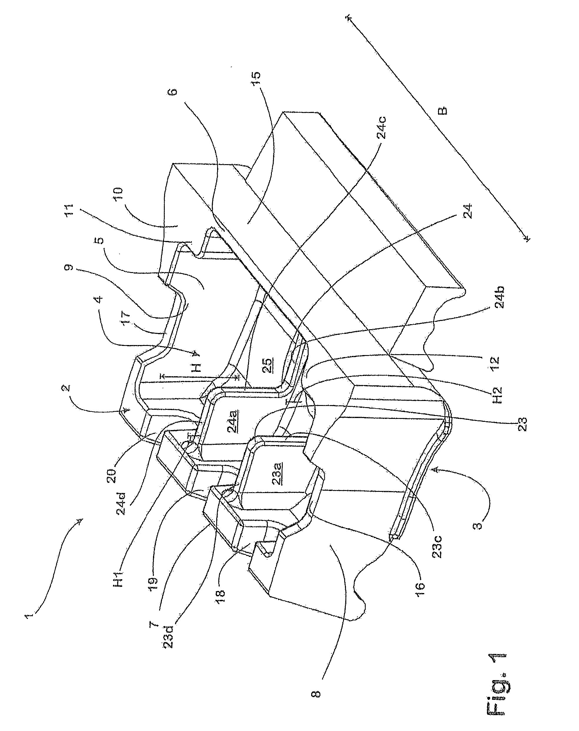
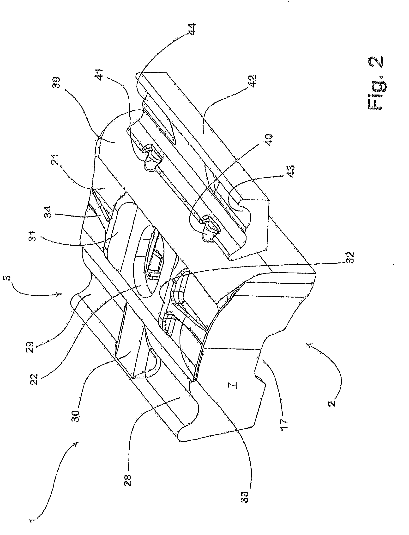
[0056]The guide plate 1, which has the basic shape of a cuboid and is made in one piece from a fibre-reinforced plastic, has an underside 2 and an upper side 3 which is remote from the underside 2 and is exposed in the installation position.

[0057]A recess 4, the opening 5 of which takes up the vast majority of the underside 2, is shaped into the guide plate 1 from its underside 2. In this case, the recess 4 is bounded by a first longitudinal side wall 6 associated with the rail to be installed, a rearward second longitudinal side wall 7 arranged opposite thereto, a first narrow side wall 8 extending on one narrow side of the guide plate 1 and a second narrow side wall 9 which is arranged opposite thereto and is associated with the other narrow side of the guide plate 1.

[0058]The surfaces of the longitudinal sides 6, 7 and the narrow sides 8, 9 that are associated with the underside 2 form a standing surface 10 with which the guide plate 1 is positioned on the respective substrate in...


PUM

PropertyMeasurementUnit
heightaaaaaaaaaa
plasticaaaaaaaaaa
breaking pointaaaaaaaaaa

Abstract

The invention relates to a guide plate for a system for fastening a rail to a substrate on which there is provided, laterally of the railway track, a shoulder, which absorbs the forces occurring when the rail is traveled on by a rail vehicle, the guide plate having an underside which is associated with the substrate and an upper side which is exposed in the installation position, is remote from the underside and on which it is possible to support a spring element provided for applying resiliently elastic holding-down forces to the rail to be fastened.

Description

CROSS REFERENCE TO RELATED APPLICATION[0001]This application is a continuation-in-part of International Patent Application No. PCT / EP2009 / 051588, filed Feb. 11, 2009, which is herein incorporated by reference in its entirety.BACKGROUND OF THE INVENTION[0002]1. Field of the Invention[0003]The invention relates to a guide plate for a system for fastening a rail to a substrate on which there is provided, laterally of the railway track, a shoulder which absorbs the forces which are produced when a rail vehicle travels on the rail. The guide plate has in this case an underside which is associated with the substrate and an upper side which is exposed in the installation position, is arranged remote from the underside and on which it is possible to support a spring element provided for applying resiliently elastic holding-down forces to the rail to be fastened.[0004]In addition, the invention relates to a system for fastening a rail to a substrate on which there is provided, laterally of t...

Claims


Application Information

Patent Timeline
Patent Type & Authority Applications(United States)
IPC IPC(8): E01B9/00
CPCY10T29/53E01B9/30E01B9/303
Inventor BOSTERLING, WINFRIEDRADEMACHER, LUTZESFANDIYARI, FARHADSTEIDL, MICHAEL
Owner VOSSLOH WERKE GMBH
Why Eureka
Try Eureka