Well collision avoidance using distributed acoustic sensing

Inactive Publication Date: 2010-08-12
SHELL OIL CO
View PDF44 Cites 83 Cited by
  • Summary
  • Abstract
  • Description
  • Claims
  • Application Information

AI Technical Summary

Benefits of technology

[0007]The present invention provides an acoustic monitoring system that is relatively inexpensive to acquire, deploy, and maint

Problems solved by technology

Existing wells on production at an offshore platform or onshore well pad are under significant risk when a new well is drilled, or an existing well is re-drilled, from the same facility or one in the vicinity.
The risk is due to the possibility of collision of the drill bit or other drilling apparatus in the new well with the casing and/or well tubing of the existing wells.
Such a collision would result in damage to equipment and to the wellbores themselves, which is costly to repair (and also introduces further risk), and could result in an undesired release of hydrocarbons, possibly without effective means to control.
Existing tools and techniques for avoiding collision are based on measurement-while-drilling and other surveys, which may not have sufficient accuracy to

Method used


Image

  • Well collision avoidance using distributed acoustic sensing
  • Well collision avoidance using distributed acoustic sensing

Examples


Embodiment Construction

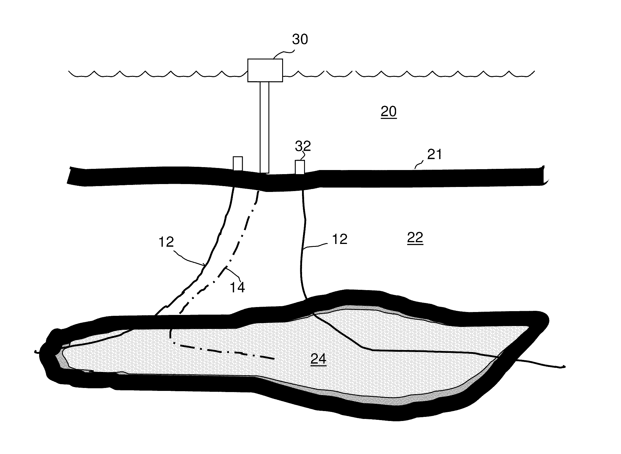
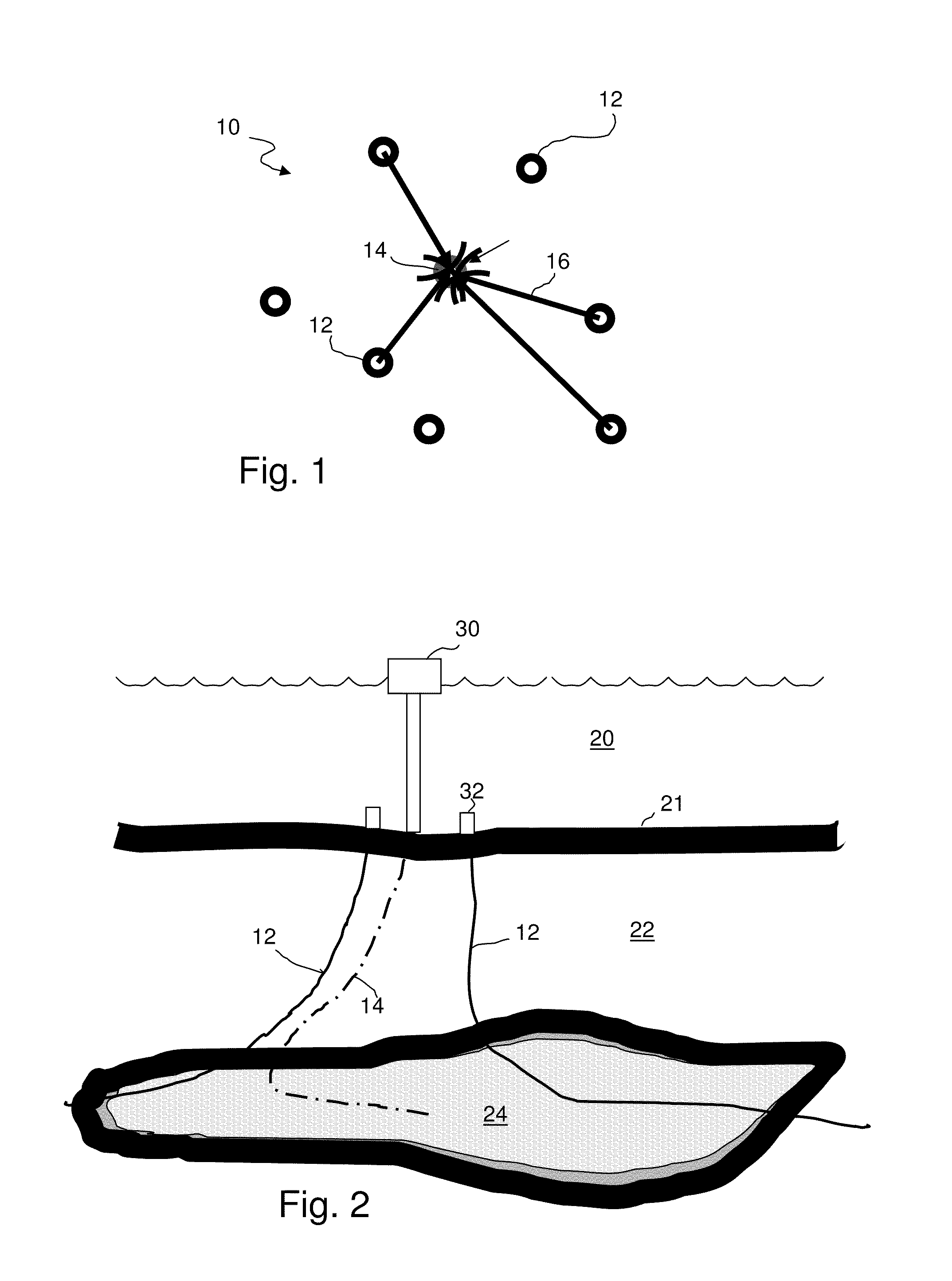
[0017]Referring initially to FIGS. 1 and 2, an offshore environment 10 includes a plurality of existing wells 12 and a new well 14 (shown in phantom) typically located in some depth of water 20. The wells extend through the seafloor 21 and into a subsurface 22. Subsurface 22 includes a target formation 24. As shown in FIG. 2, each well extends from the seafloor along a desired trajectory. New well 14 will typically be drilled from a platform 30, or the like, as is known.

[0018]In the illustrated system, it is desired to drill well 14 along the trajectory shown, in order to maximize contact with the target formation 24 and therefore maximize production from well 14. Wells 12 are close enough to the desired trajectory of well 14 that there may be a risk that well 14 will intersect the trajectory of one of wells 12 if the trajectory of well 14 is not adequately guided during drilling or if the trajectory of wells 12 are not known with sufficient accuracy or certainty.

[0019]It has been f...


PUM


Abstract

A method for obtaining location information about a well as it is being drilled through a subsurface, comprises: providing at least one fiber optic cable deployed in a borehole within acoustic range of the well, the proximal end of the cable being coupled to a light source and a photodetector, the fiber optic cable being acoustically coupled to the subsurface formation so as to allow acoustic signals in the subsurface to affect the physical status of the cable, providing an acoustic source in the well, transmitting at least one light pulse into the cable, receiving at the photodetector a first light signal indicative of the physical status of at least one first section of the cable. The first section is selected so that the first light signal provides information about the position of the acoustic source, and outputting at least the information to a display.

Description

RELATED CASES[0001]This case claims priority to U.S. provisional application 61 / 150842, filed Feb. 9, 2009 and entitled “Method Of Detecting Fluid In-Flows Downhole,” which is incorporated herein by reference.FIELD OF THE INVENTION[0002]The invention relates to the use of fiber optic cables to provide a system of distributed acoustic sensors that can be used to provide information about the position of various subsurface objects and in particular to locate existing wellbores during drilling.BACKGROUND OF THE INVENTION[0003]Existing wells on production at an offshore platform or onshore well pad are under significant risk when a new well is drilled, or an existing well is re-drilled, from the same facility or one in the vicinity. The risk is due to the possibility of collision of the drill bit or other drilling apparatus in the new well with the casing and / or well tubing of the existing wells. Such a collision would result in damage to equipment and to the wellbores themselves, which...

Claims


Application Information

Patent Timeline
IPC IPC(8): G01V8/00E21B47/02
CPCE21B47/02208G01V1/42E21B47/123E21B47/0224E21B47/135
Inventor FORSTER, LARRY DALERAMBOW, FREDERICK HENRY KREISLERDRIA, DENNIS EDWARDGRANT, LISA SHAVACOLLINS, CHARLES LOUIS
Owner SHELL OIL CO
Why Eureka
Try Eureka