Transmission noise suppressing structure and wiring circuit board

a technology of transmission noise and wiring circuit, which is applied in the direction of line-transmission details, waveguide types, waveguides, etc., can solve the problems of high speed, multi-functionality, and complexity of mpus (microprocessor units) in servers, and the quality of a signal waveform is easily deteriorated, so as to reduce the crosstalk of signal transmission lines, suppress the transmission noise of power supply lines, and stabilize the power supply voltage

Inactive Publication Date: 2010-08-12
SHIN-ETSU POLYMER CO LTD
View PDF2 Cites 9 Cited by
  • Summary
  • Abstract
  • Description
  • Claims
  • Application Information

AI Technical Summary

Benefits of technology

[0021]A transmission noise suppressing structure and a wiring circuit board according to the invention is capable of suppressing a transmission noise of a power supply line, stabilizing a power supply voltage, and reducing signal transmission line cross talk transmitted through the power supply line or a ground layer without being affected by a resistive layer.

Problems solved by technology

Moreover, high speed, multi-functionality, and complexity of MPUs (Microprocessor Units) have been realized in servers, workstations, PCs, cellular phones, and game consoles.
However, a problem with a malfunction in these apparatuses or other electronic apparatuses may arise due to a noise transmitted from these apparatuses or a noise caused in a conducting member of an apparatus.
However, the high resistant loss layer connected to the power supply layer occupies a large area.
For this reason, when the high resistant loss layer is disposed to be connected to the power supply line, problems may arise in that the quality of a signal waveform easily deteriorates, such as cross talk in the signal transmission line, delay of signal transmission, or non-exceeding of a threshold value caused due to reduction in a voltage.

Method used


Image

  • Transmission noise suppressing structure and wiring circuit board
  • Transmission noise suppressing structure and wiring circuit board
  • Transmission noise suppressing structure and wiring circuit board

Examples


first embodiment

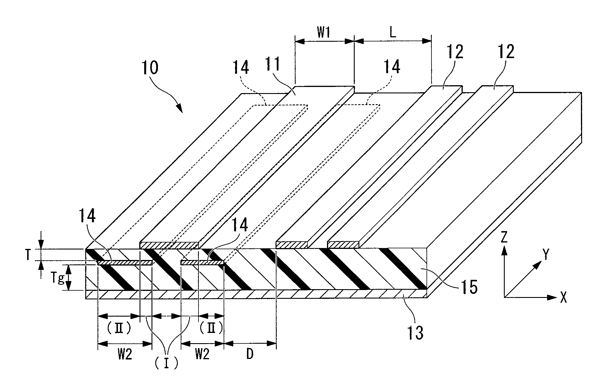
[0066]FIG. 1 is a perspective view illustrating the cross section of a transmission noise suppressing structure according to a first embodiment of the invention. A transmission noise suppressing structure 10, which is a double-side board, includes: a power supply line 11 and two signal transmission lines 12 arranged apart from each other side by side in a Y direction on the front surface (the same surface) of the board; a surface ground layer 13 disposed apart from the power supply line and the signal transmission lines so as to face the power supply line 11 and the signal transmission lines 12 with an insulating layer 15 interposed therebetween and covering the entire rear surface of the board; and two resistive layers 14 arranged in the Y direction apart from the power source line and the ground layer so as to face the power source line 11 and the ground layer 13 with the insulating layer 15 interposed therebetween.

[0067]The two resistive layers 14 are disposed apart on the same s...

second embodiment

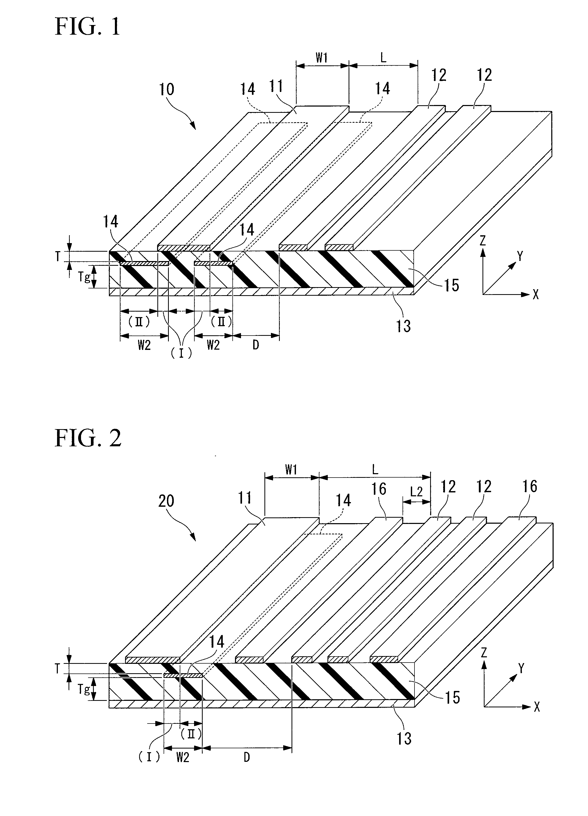
[0083]FIG. 2 is a perspective view illustrating the cross section of a transmission noise suppressing structure according to a second embodiment of the invention.

[0084]A transmission noise suppressing structure 20, which is a double-side board, includes: a power supply line 11 and two signal transmission lines 12 arranged apart from each other side by side in a Y direction on the front surface (the same surface) of the board; a surface ground layer 13 disposed apart from the power supply line and the signal transmission lines so as to face the power supply line 11 and the signal transmission lines 12 with an insulating layer 15 interposed therebetween and covering the entire rear surface of the board; a resistive layer 14 arranged in the Y direction apart from the power source line and the ground layer so as to face the power source line 11 and the ground layer 13 with the insulating layer 15 interposed therebetween; and two ground lines 16 disposed between the power supply line 11 ...

third embodiment

[0093]FIGS. 9 and 10 are diagrams illustrating the transmission noise suppressing structure according to a third embodiment of the invention. FIG. 10 is a top view and FIG. 9 is a sectional view taken along the line A-A′ of FIG. 10.

[0094]The transmission noise suppressing structure 10 according to this embodiment is a double-side board in which the power supply line 11 and the signal transmission lines 12 are disposed on the front surface and the ground layer 13 is disposed on the rear surface. The power supply line 11 and the signal transmission lines 12 are disposed on the same surface and arranged side by side apart from each other. The resistive layer 14 is disposed between the power supply line 11 and the ground layer 13.

[0095]The ground layer 13 is disposed apart from the power supply line and the signal transmission line so as to face the power supply line 11 and the signal transmission line 12, and the resistive layer 14 is disposed apart from the power supply line and the g...


PUM


Abstract

The invention provides a transmission noise suppressing structure and a wiring board capable of suppressing a transmission noise transferred through a power supply line, stabilizing a power supply voltage, and reducing signal transmission line cross talk transmitted through the power supply line or a ground layer without being affected by a resistive layer. A transmission noise suppressing structure includes a power supply line and a signal transmission line arranged apart from each other on the same surface; a ground layer arranged apart from the power supply line and the signal transmission line; and a resistive layer arranged apart from the power supply line and the ground layer. The resistive layer has an area (I) which faces the power supply line and an area (II) which does not face the power supply line. The resistive layer and the signal transmission line are apart from each other.

Description

TECHNICAL FIELD[0001]The present invention relates to a conductive noise suppressing structure and a wiring circuit board including the conductive noise suppressing structure.[0002]Priority is claimed on Japanese Patent Application No. 2007-202121, filed on Aug. 2, 2007 and Japanese Patent Application No. 2007-277769, filed on Oct. 25, 2007, the content of which is incorporated herein by reference.BACKGROUND OF THE INVENTION[0003]In recent years, with the development of a ubiquitous society, electronic apparatuses such as information processing apparatuses (servers, workstations, PCs, game consoles, etc.) and communication apparatuses (cellular phone, etc.) have improved in a signal transmission rate due to the optical / electric conversion of an optical module and have been miniaturized. Moreover, high speed, multi-functionality, and complexity of MPUs (Microprocessor Units) have been realized in servers, workstations, PCs, cellular phones, and game consoles. High speed has been real...

Claims


Application Information

Patent Timeline
Patent Type & Authority Applications(United States)
IPC IPC(8): H01P1/20
CPCH01P3/08H05K1/0234H05K1/167H05K2201/09672H05K2201/09318H05K2201/09336H05K2201/09236
Inventor KAWAGUCHI, TOSHIYUKITAHARA, KAZUTOKISAGA, TSUTOMU
Owner SHIN-ETSU POLYMER CO LTD
Why Eureka
Try Eureka