Roller type stamper

a stamper and roller technology, applied in the field of roller type stampers, can solve the problems of reducing the transfer rate, reducing the production cost of optical plates, and limiting the pressure at which resin is injected, so as to achieve excellent release characteristics, prevent or reduce defects in optical resins, and strong adhesion to metals.

Inactive Publication Date: 2010-08-12
SAMSUNG MOBILE DISPLAY CO LTD
View PDF16 Cites 9 Cited by
  • Summary
  • Abstract
  • Description
  • Claims
  • Application Information

AI Technical Summary

Benefits of technology

[0015]In a roller type stamper according to exemplary embodiments of the present invention, a silicon material is used as a finishing material along the connecting portion, the silicon material having strong adhesion to metal and excellent release characteristics from optical resin, thereby preventing or reducing defects in the optical resin generated by a groove at the connecting portion, such that a resin coating layer is not formed to be thicker in regions coming into contact with the connecting portion.

Problems solved by technology

However, in the injection method, a transfer rate is lowered when micro-patterns of several tens of micrometers (μm) are formed, and a pressure at which resin is injected is therefore limited.
Therefore, it is difficult to manufacture optical plates and the like having a large size of, for example, over 17 inches, and mass production is hindered.

Method used


Image

  • Roller type stamper
  • Roller type stamper
  • Roller type stamper

Examples


Embodiment Construction

[0021]In the following detailed description, only certain exemplary embodiments of the present invention have been shown and described by way of illustration. As those skilled in the art would realize, the described embodiments may be modified in various different ways without departing from the spirit or scope of the present invention. Accordingly, the drawings and description are to be regarded as illustrative in nature and not restrictive. In addition, when an element is referred to as being “on” another element, it may be directly on the another element, or may be indirectly on the another element, with one or more elements interposed therebetween. Also, when an element is referred to as being “connected to” another element, it may be directly connected to the another element, or may be indirectly connected to the another element, with one or more elements connected therebetween. Hereinafter, like reference numerals refer to like elements.

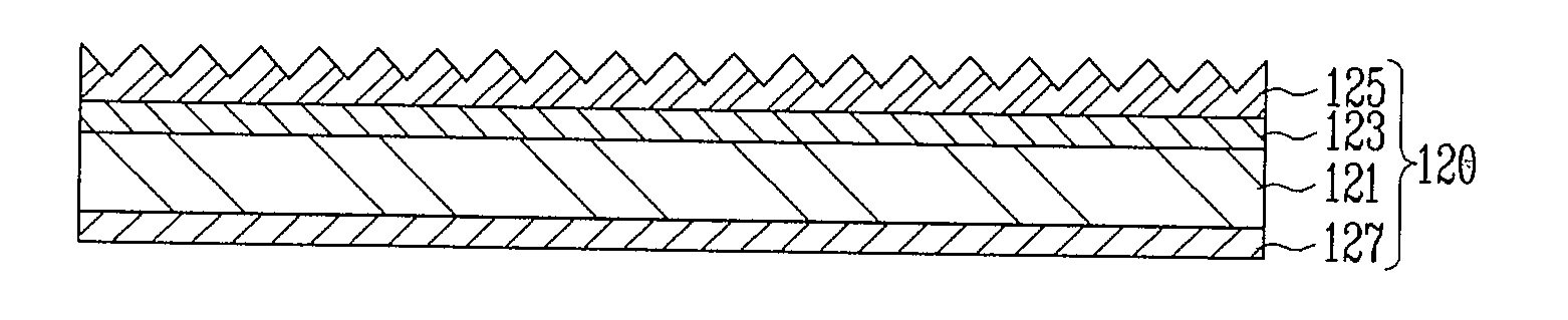
[0022]FIG. 1 is a cross-sectional view o...


PUM

PropertyMeasurementUnit
sizeaaaaaaaaaa
adhesionaaaaaaaaaa
self-luminescentaaaaaaaaaa

Abstract

A roller type stamper includes a roller; a stamper film including a first surface having a pattern, and a second surface opposite the first surface and connected to an outer circumferential surface of the roller at least one connecting portion; and a planarizing portion for filling a groove approximate the at least one connecting portion.

Description

CROSS-REFERENCE TO RELATED APPLICATIONS[0001]This application claims priority to and the benefit of Korean Patent Application No. 10-2009-0010141, filed on Feb. 9, 2009, in the Korean Intellectual Property Office, the entire content of which is incorporated herein by reference.BACKGROUND OF THE INVENTION[0002]1. Field of the Invention[0003]The present invention relates to a roller type stamper.[0004]2. Description of Related Art[0005]A liquid crystal display device is a non-emissive device in which a display panel for displaying images is not self-luminescent. Therefore, a separate backlight unit is required to supply light to the display panel.[0006]The backlight unit includes a light source for emitting light, and optical plates, such as a light guide plate and a diffusion plate, which improve the efficiency of light emitted from the light source.[0007]Accordingly, patterns having specific shapes such as prisms or hemispheres may be formed on the optical plates so as to improve li...

Claims


Application Information

Patent Timeline
Patent Type & Authority Applications(United States)
IPC IPC(8): B28B5/10B28B3/16
CPCB29C35/02B29C37/0067B29C59/046B29K2069/00G02B6/0065G02F1/1303G02F1/133504G02F2001/133607G02B6/0053B29L2011/00G02F1/133607B29C59/04G02F1/13G02F1/1335
Inventor CHOI, CHAN-IEKCHO, WON-KI
Owner SAMSUNG MOBILE DISPLAY CO LTD
Why Eureka
Try Eureka