Dynamic stabilization device for bones, in particular for vertebrae

a stabilization device and bone technology, applied in the field of bones, can solve the problems of unsatisfactory simulation of the properties of a natural intervertebral disc, unnatural stress of the vertebral column adjacent to the stiffened section, and inability to achieve the effect of guiding stability of the movement segment of the vertebral column by using a band of this kind

Inactive Publication Date: 2010-08-12
BIEDERMANN TECH GMBH & CO KG
View PDF8 Cites 55 Cited by
  • Summary
  • Abstract
  • Description
  • Claims
  • Application Information

AI Technical Summary

Benefits of technology

[0018]The invention also provides a method for stabilizing vertebrae adjacent to a defective intervertebral disc. The method comprises the following steps: providing a dynamic stabilization device comprising a first bone anchoring element, a second bone anchoring element, a rigid rod having a longitudinal axis connecting the two bone anchoring elements and an elastic element between the first and the second bone anchoring element and acting on the first and the second bone anchoring element to exert a force in a direction of the longitudinal axis, wherein each bone anchoring element comprises a first section to be anchored in a bone and a second section to be connected to the rod, and wherein at least one of the bone anchoring elements comprising a polyaxial bone screw; attaching the first and second bone anchoring elements to two vertebrae on opposite sides of the defective intervertebral disc; aligning the second section of both of the first and second bone anchoring elements to connect the rod therebetween with the elastic element positioned between the first and second bone anchoring elements; and fixedly connecting at least one of the bone anchoring elements to the rod so as to prevent translational movement of the rod relative to the at least one of the bone anchoring elements.

Problems solved by technology

In the first case, the sections of the vertebral column adjacent to the stiffened section are unnaturally stressed and, in the second case, simulation of the properties of a natural intervertebral disc is still unsatisfactory.
The use of a band of this kind does not however produce any guidance stability of the movement segment of a vertebral column.
Nor is it possible to adjust the adjacent vertebrae in their positioning relative to one another, because the force transmission behaviour of the band and the pressure element via the bone screws is non-specific.
Furthermore, the force transmission behaviour of the damping element is undefined, as it yields not only to axial, but also to bending and torsional forces.
However, with this implant system it is not possible to provide for dynamic movement control of the intervertebral disc or for dynamic takeover of stress to relieve the stress on a intervertebral disc.

Method used


Image

  • Dynamic stabilization device for bones, in particular for vertebrae
  • Dynamic stabilization device for bones, in particular for vertebrae
  • Dynamic stabilization device for bones, in particular for vertebrae

Examples


Embodiment Construction

Including Preferred Embodiments

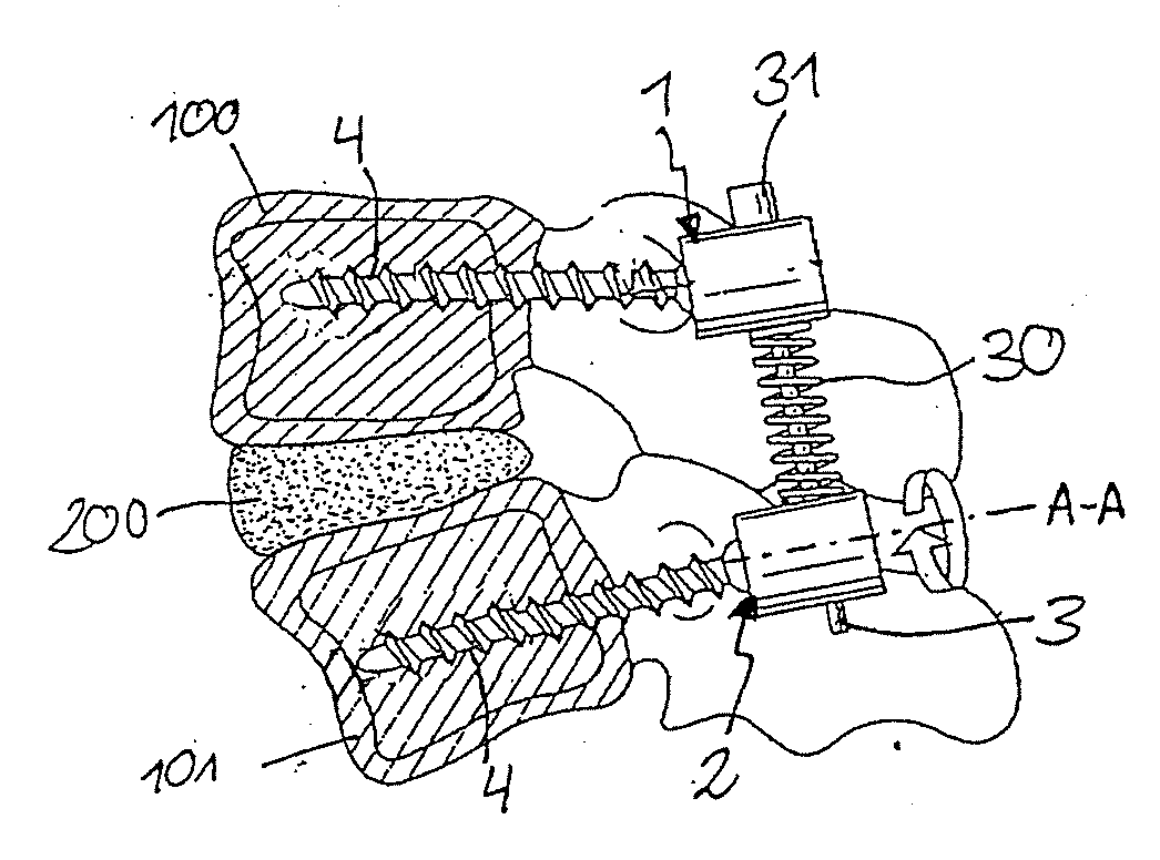
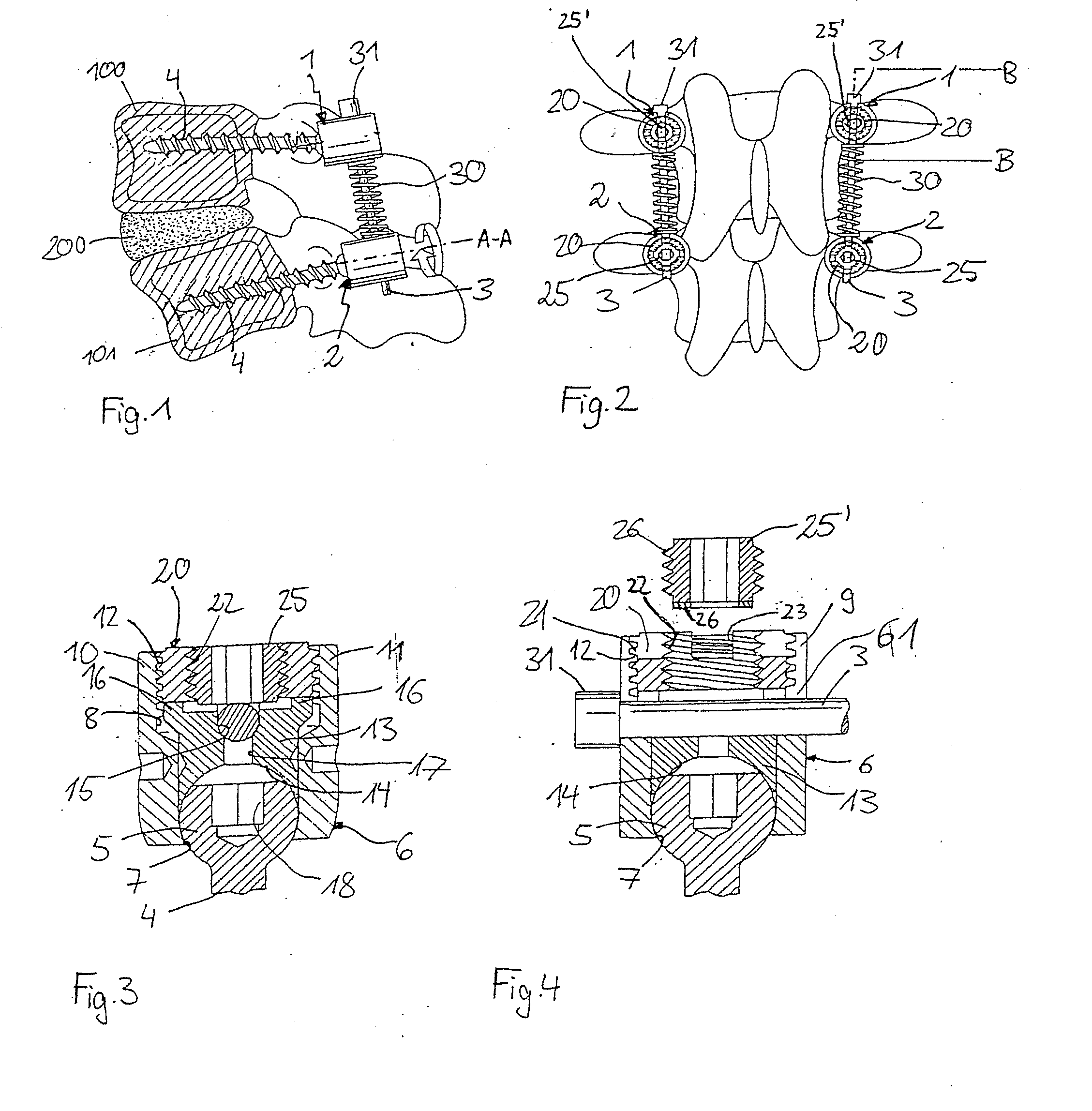
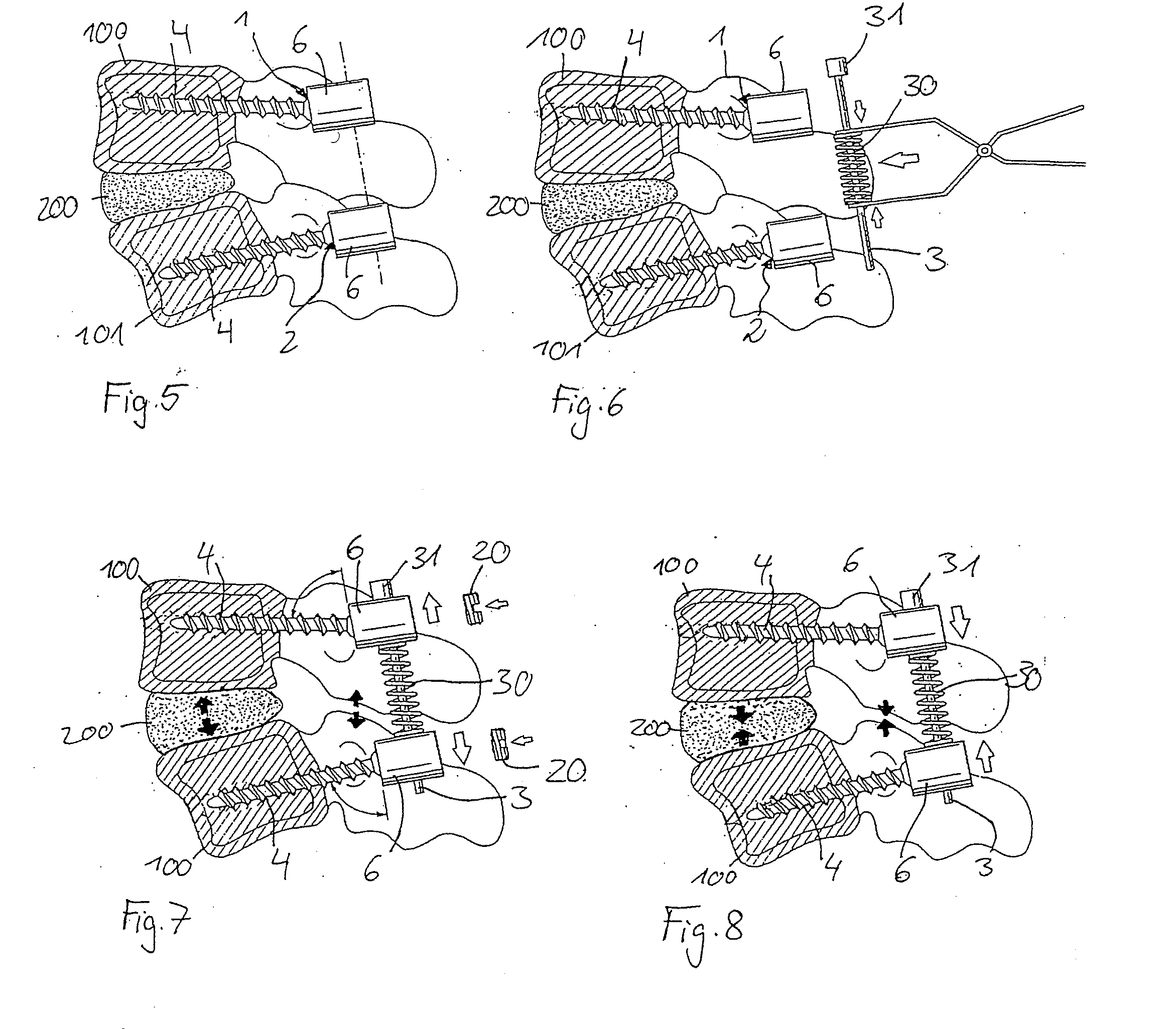
[0025]The invention is now described in detail with reference to the embodiment illustrated in FIGS. 1 to 4. A stabilization device in accord with one embodiment of the present invention has two polyaxial pedicle screws 1, 2 and a rod 3 connecting them for stabilizing two adjacent vertebrae 100, 101. The stabilization device further contains a spring element 30, provided between the two pedicle screws.

[0026]The pedicle screws 1, 2 preferably are constructed as illustrated in FIGS. 3 and 4. A pedicle screw 1, 2 has a screw element with a threaded shank 4 with a bone thread and a head 5 shaped like a segment of a sphere, which is connected to a receiving part 6. The receiving part 6 has on one of its ends a first bore 7, aligned symmetrically to the axis, the diameter of which is larger than that of the threaded section of the shank 4 and smaller than that of the head 5. It further has a coaxial second bore 8 which is open at the end opposite the first b...


PUM


Abstract

A dynamic stabilization device for bones, in particular vertebrae, is made with two bone anchoring elements and a rigid rod with a longitudinal axis connecting them. An elastic element is inserted between the two bone anchoring elements. It acts on the bone anchoring elements to exert a force in a direction of the longitudinal axis. Each bone anchoring element has a first section to be anchored in a bone and a second section to be connected to the rod. At least one of the bone anchoring elements is fixedly connected to the rod to prevent translational movement of the rod relative to it. Further, at least one of the bone anchoring elements is a polyaxial bone screw. Also disclosed is a method for stabilizing vertebrae adjacent to a defective intervertebral disc. A dynamic stabilization device is provided. The anchoring elements are attached to two vertebrae on opposite sides of the defective intervertebral disc. Then, the bone anchoring elements are alligned to connect the rod therebetween with the elastic element positioned between the bone anchoring elements. Finally, one of the bone anchoring elements is connected fixedly to the rod to prevent translational movement of the rod relative to it.

Description

FIELD OF THE INVENTION[0001]The invention relates to a dynamic stabilization device for bones, in particular for vertebrae, preferably with at least one first and one second bone anchoring element, and a rod connecting the bone anchoring elements, wherein each bone anchoring element has a first section to be anchored in a bone and a second section to be connected to a rod, and wherein the bone anchoring elements can optionally be connected to the rod rigidly or as displaceable in the direction of the shaft of the rod.BACKGROUND OF THE INVENTION[0002]A known method for treating intervertebral disc defects is removal by operation of the defective intervertebral disc and stiffening the intervertebral disc space with two vertebral bodies or, after removal of the defective intervertebral disc, subsequent insertion of an artificial intervertebral disc. In the first case, the sections of the vertebral column adjacent to the stiffened section are unnaturally stressed and, in the second case...

Claims


Application Information

Patent Timeline
Patent Type & Authority Applications(United States)
IPC IPC(8): A61B17/70A61B17/58A61B17/00
CPCA61B17/7008A61B17/702A61B2017/00845A61B17/7035A61B17/7032A61B17/70
Inventor BIEDERMANN, LUTZJESZENSKY, DEZSO
Owner BIEDERMANN TECH GMBH & CO KG
Why Eureka
Try Eureka