Method and system for positional measurement using ultrasonic sensing

a positional measurement and ultrasonic sensing technology, applied in the field of motion sensing, can solve the problems of /b> not matching the actual location of the object, the vibration of the haptic module may change (increase/decrease) and the vibration of the signal to noise ratio

Inactive Publication Date: 2010-08-12
ORTHOSENSOR
View PDF38 Cites 96 Cited by
  • Summary
  • Abstract
  • Description
  • Claims
  • Application Information

AI Technical Summary

Problems solved by technology

As an example, the haptic module may change (increase / decrease) vibration to signal improper or proper operation.
However, if the relative displacements 438 are imprecise, then over time, the expected location 432 may not match an actual location of the object.

Method used


Image

  • Method and system for positional measurement using ultrasonic sensing
  • Method and system for positional measurement using ultrasonic sensing
  • Method and system for positional measurement using ultrasonic sensing

Examples


Embodiment Construction

[0013]While the specification concludes with claims defining the features of the invention that are regarded as novel, it is believed that the invention will be better understood from a consideration of the following description in conjunction with the drawing figures, in which like reference numerals are carried forward.

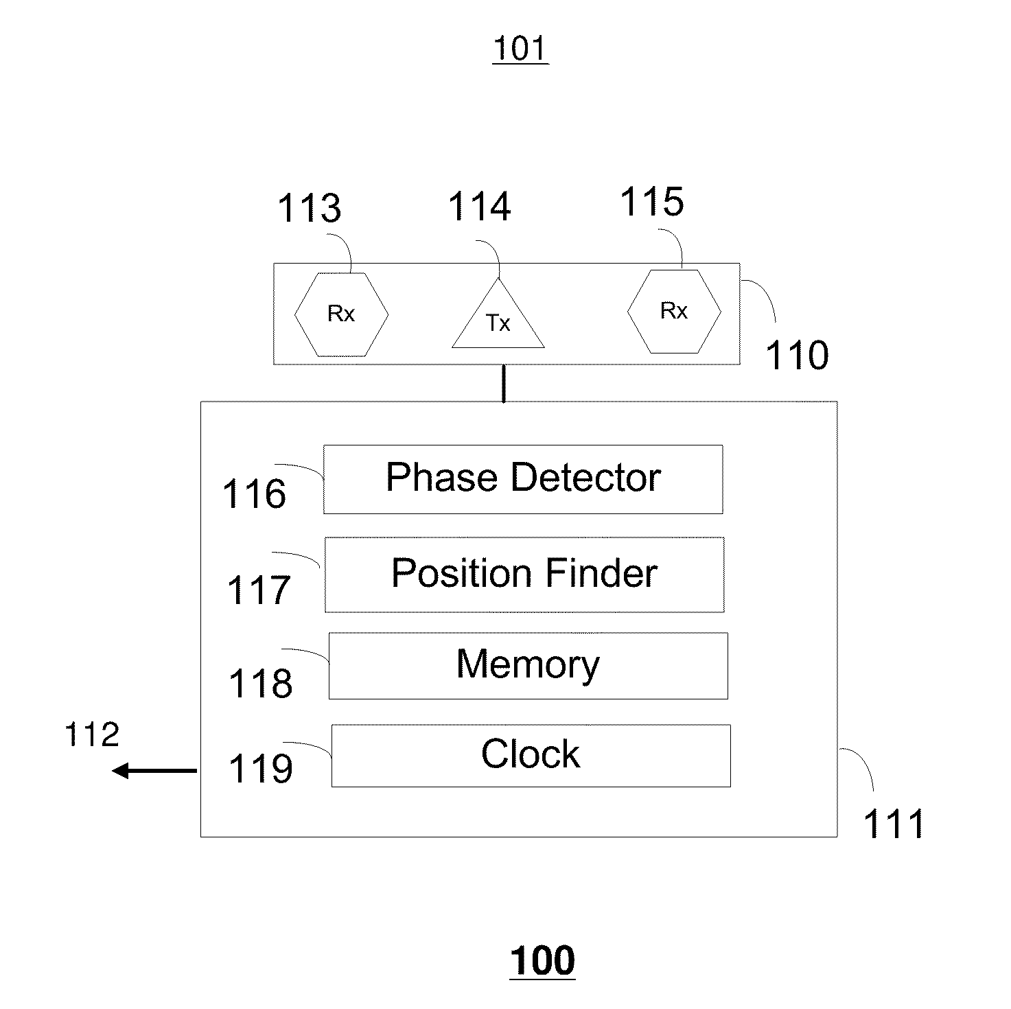
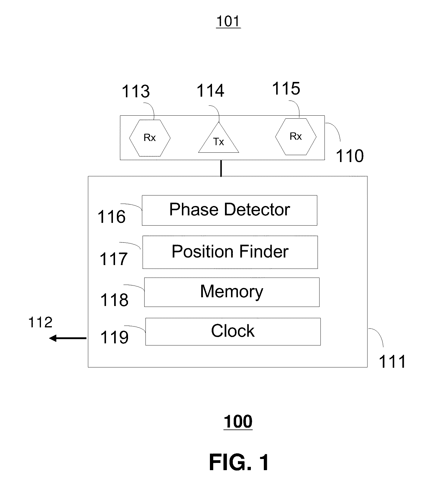
[0014]Referring to FIG. 1, an ultrasonic device 100 is shown. The ultrasonic device 100 includes a sensing unit 110 for creating an ultrasonic sensing space, and a controller 111 for operating the sensing unit 110. The ultrasonic device 100 detects movement and location of an object in the ultrasonic sensing space 101. A display 112 can be coupled to the ultrasonic device 100 for showing the movement or position of the object. The sensing unit 110 can include an ultrasonic transmitter 114, a first receiver 113 and a second receiver 115 for sensors. The sensors can be ultrasonic transducers, acoustic microphones, Micro Electro Mechanical Element (MEMS) microphones, o...


PUM


Abstract

A method for determining position and alignment is provided. The method includes monitoring a first and second sequence of ultrasonic signals transmitted from the first device to a second device, estimating a location of the first device from Time of Flight measurements of the ultrasonic signals at respective microphones on the second device, calculating a set of phase differences, weighting a difference of an expected location and estimated location of the first device with the set of phase differences to produce a relative displacement, and reporting a position of the first device based on the relative displacement.

Description

CROSS-REFERENCE TO RELATED APPLICATION[0001]This application is a Continuation-In-Part of U.S. patent application Ser. No. 11 / 562,404 filed on Nov. 21, 2006 claiming the priority benefit of U.S. Provisional Patent Application No. 60 / 740,151 filed Nov. 28, 2005, the entire contents of which are hereby incorporated by reference. This application also claims priority benefit to Provisional Patent Application No. 61 / 291,725 filed Dec. 31, 2009, the entire contents of which are hereby incorporated by reference.BACKGROUND[0002]1. Field[0003]The present embodiments of the invention generally relates to the field of motion sensing, and more particularly to input pointing devices.[0004]2. Introduction[0005]Motion detection systems can include radar systems, video camera monitoring systems, and medical diagnostic systems. Motion detection systems generally include a sensor which converts a physical signal into an electronic signal. The sensor performs the task of capturing the signal and conv...

Claims


Application Information

Patent Timeline
Patent Type & Authority Applications(United States)
IPC IPC(8): G01B17/00
CPCA61B19/5244A61B2019/5483A61B2019/5425A61B2019/5263A61B34/20A61B2034/2063A61B2090/3925A61B2090/3983
Inventor ROCHE, MARTINBOILLOT, MARCMCINTOSH, JASON
Owner ORTHOSENSOR
Why Eureka
Try Eureka