Image Alignment and Trend Analysis Features for an Infrared Imaging System

an infrared imaging and trend analysis technology, applied in the field ofthermography, can solve the problems of use of such tools, and inability to accurately identify the actual camera location over a number of times

Active Publication Date: 2010-08-12
THERMOTEKNIX SYSTEMS LTD
View PDF31 Cites 25 Cited by
  • Summary
  • Abstract
  • Description
  • Claims
  • Application Information

AI Technical Summary

Problems solved by technology

Each of these schemes has drawbacks.
Neither of the schemes mentioned is highly accurate, leading to imprecision in actual camera location over a number of images.
The use of such tools, however, adds time and complexity to the processing of a series of images.
Another drawback of conventional thermographic image alignment schemes is the lack of a convenient way to display the desired tool settings for capturing the next in a series of conditional monitoring images.
Locating the tool(s) on the respective thermographic images is generally a painstaking process that requires each image to be worked individually.

Method used


Image

  • Image Alignment and Trend Analysis Features for an Infrared Imaging System
  • Image Alignment and Trend Analysis Features for an Infrared Imaging System
  • Image Alignment and Trend Analysis Features for an Infrared Imaging System

Examples


Embodiment Construction

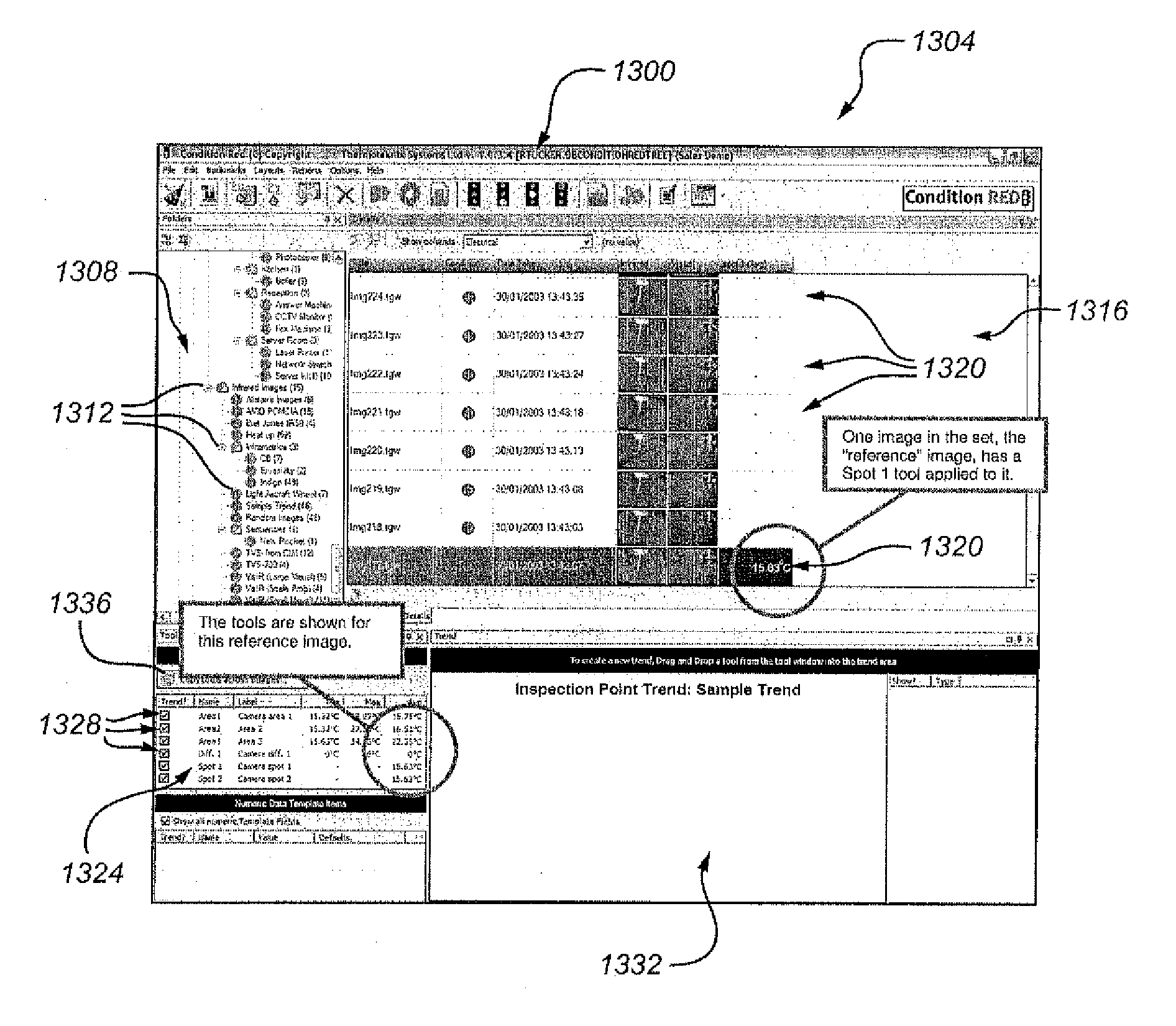
[0033]At a relatively high level, the present disclosure is directed to features, variations of these features and ways of implementing these feature for assisting thermographers and others in efficiently and effectively implementing and carrying out a condition monitoring program. As described in the Background section above, condition monitoring involves capturing a series of thermographic images of a particular subject over a period of time. This series of thermographic images allows a user to track the trend(s) of any one or more temperatures of interest, e.g., maximum temperature, minimum temperature or temperature at a particular location on the subject at issue. Preferably, the thermographic images are captured by a thermographic imaging device located at the same location and orientation each time, and using the same thermographic camera settings, so as to maintain consistency throughout the series.

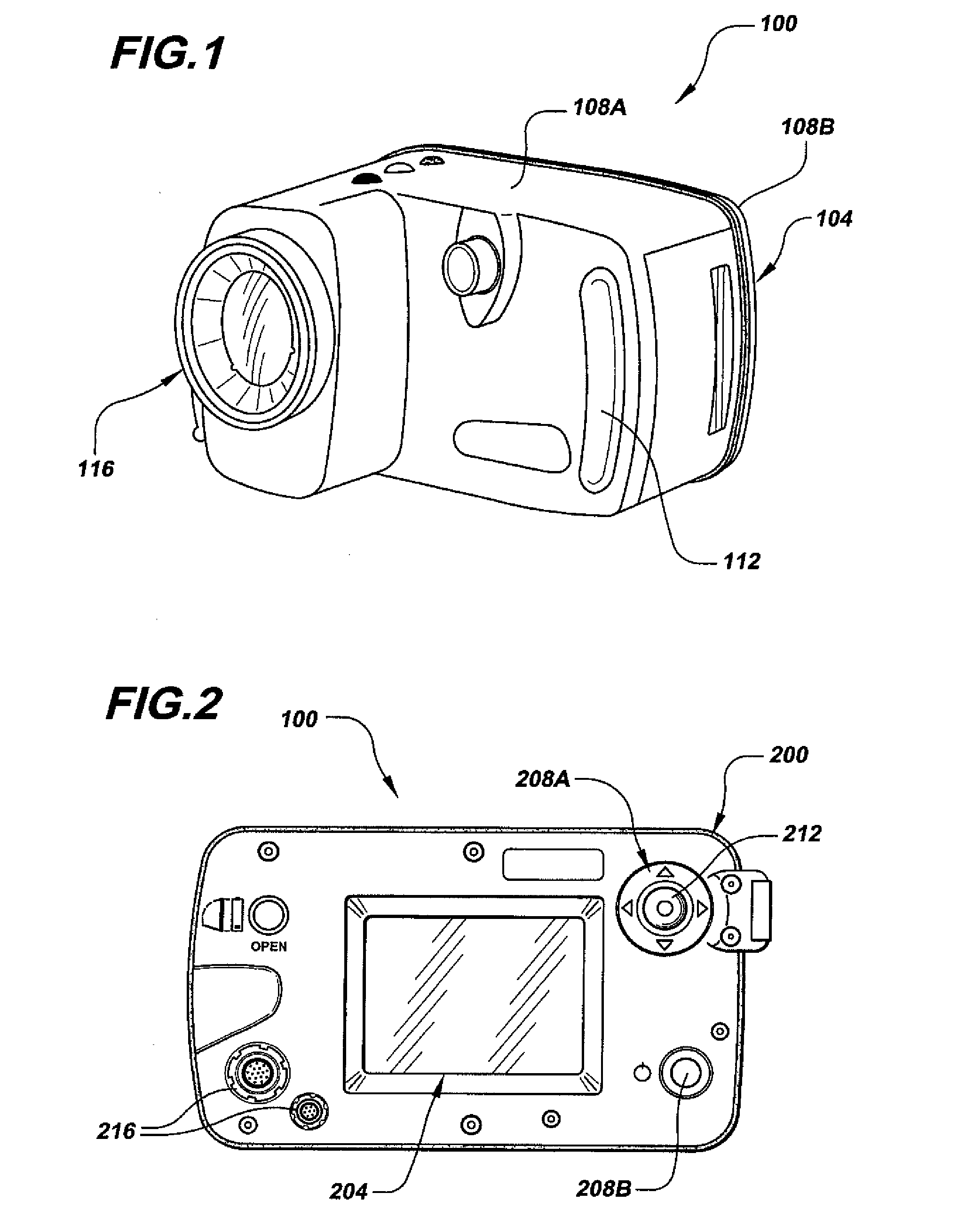
[0034]Referring now to the drawings, FIG. 1 illustrates an example 100 of a t...


PUM


Abstract

In one embodiment, a thermographic imaging device having a visual compare mode that allows a user to compare a live image of a subject to a previously captured image of the same subject to aid the user in aligning the live image with the previously captured image. In this manner, a user can capture a series of images of the subject with the device located and oriented at a common location and orientation that is consistent throughout the series. In another embodiment, trend analysis software that includes a thermographic tool copying feature for copying one or more thermographic tools from a tooled thermographic image file to one or more non-tooled thermographic image files. In some embodiments, the software includes a trend-graphing feature that generates one or more trend plots after one or more tools have been copied to one or more non-tooled thermographic image files.

Description

RELATED APPLICATION DATA[0001]This application is a divisional application of U.S. Nonprovisional patent application Ser. No. 11 / 679,938, filed on Feb. 28, 2007, and titled “Image Alignment and Trend Analysis Features for an Infrared Imaging System,” and which application claims the benefit of priority of U.S. Provisional Patent Application Ser. No. 60 / 779,213, filed on Mar. 2, 2006, and titled “Image Alignment and Trend Analysis Features for an Infrared Imaging System.” Each of these applications is incorporated by reference herein in its entirety.FIELD OF THE INVENTION[0002]The present invention generally relates to the field of thermography. In particular, the present invention is directed to image alignment and trend analysis features for an infrared imaging system.BACKGROUND OF THE INVENTION[0003]Infrared (IR) thermography systems are used in a variety of settings to capture, record and / or track temperature information. For example, thermography systems are used in building ins...

Claims


Application Information

Patent Timeline
Patent Type & Authority Applications(United States)
IPC IPC(8): G06F17/30G06F3/048G01J5/00
CPCG01J5/02G01J5/025H04N5/332G01J5/505H04N5/23293G01J5/0265G01J5/03H04N23/633H04N23/632H04N23/63H04N23/11
Inventor HAIGH, PETERSALISBURY, RICHARDTUCKER, ROBIN
Owner THERMOTEKNIX SYSTEMS LTD
Why Eureka
Try Eureka