Stamping tool

a stamping tool and stamping technology, applied in the field of stamping tools, can solve problems such as wear and tear of stamping punches, and achieve the effects of convenient operation of stamping tools, operation dependability, and ease of us

Inactive Publication Date: 2010-08-19
PASS STANZTECHN
View PDF12 Cites 14 Cited by
  • Summary
  • Abstract
  • Description
  • Claims
  • Application Information

AI Technical Summary

Benefits of technology

[0018]An interruption section in accordance with claim 12 leads to a constructively simple attainment of a securing ring which can be shifted between a securing and an unlocking position.
[0019]The securing bodies in accordance with claims 13 and 14 are easy to construct and result in a dependable widening of the interruption section of the securing ring.
[0020]Pre-tensioning springs in accordance with claims 15 and 16 again increase on the one hand the operational dependability, and on the other hand the ease of operating the stamping tool.

Problems solved by technology

In the course of the operation of the stamping tool, the stamping punch wears.

Method used


Image

  • Stamping tool
  • Stamping tool
  • Stamping tool

Examples


Embodiment Construction

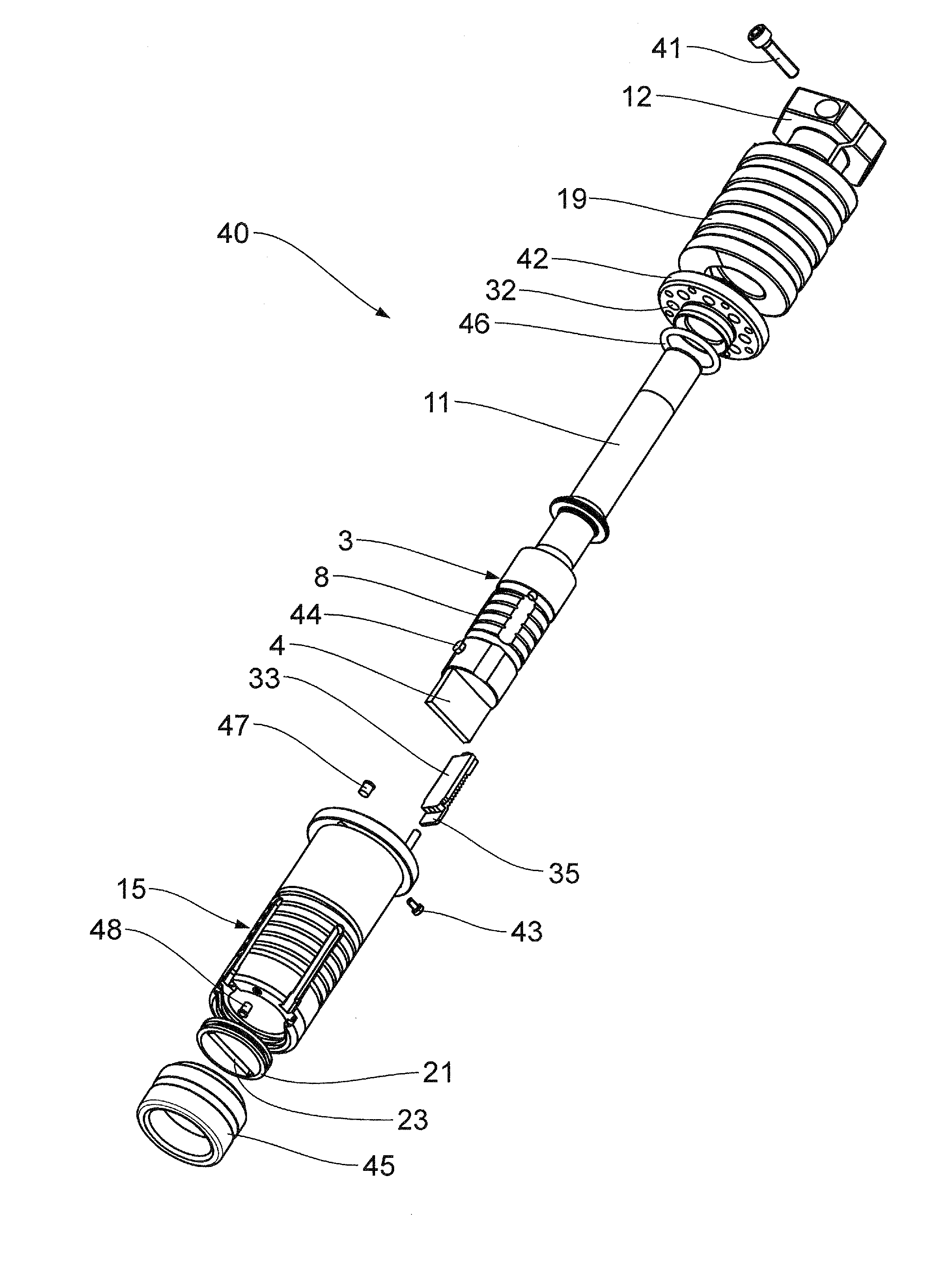
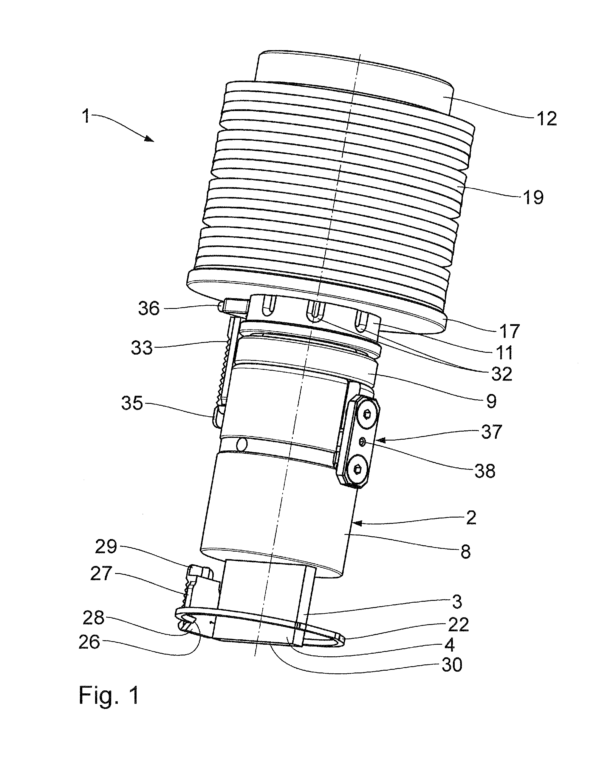
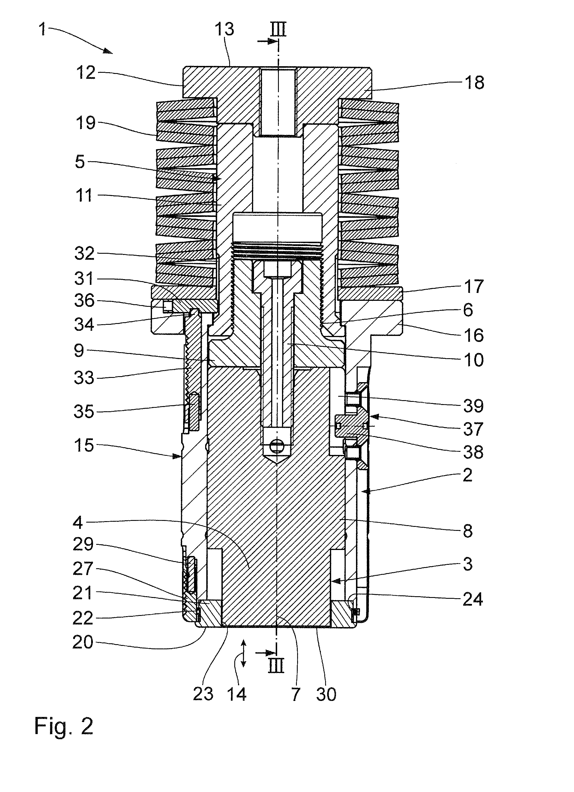
[0029]A stamping tool 1 in the embodiment in accordance with FIGS. 1 to 3 has a stamping punch 2 for forming at least one punched hole in a workpiece. The stamping punch 2 has a stamping element 3 with the stamping section 4, which comes into contact with the actual workpiece, and a head element 5, which is connected with the stamping element 3 by means of a screw connection 6.

[0030]Perpendicularly in relation to a longitudinal shaft 7 of the stamping tool 1, the stamping section 4 has a cross section corresponding to the cross section of the punched hole to be made. In the embodiment in accordance with FIGS. 1 to 3, this cross section is rectangular. Depending on the desired external shape of the punched hole, the stamping section 4 can of course also have a different, for example round, square, oval cross section, or also a special shape of a cross section, for example star-shaped.

[0031]In turn, the stamping element 3 and the head element 5 are each made of several pieces. Besides...


PUM

PropertyMeasurementUnit
lengthaaaaaaaaaa
stamping displacementaaaaaaaaaa
lengthaaaaaaaaaa

Abstract

A stamping tool has a stamping punch for forming at least one punched hole in a workpiece. The stamping punch is guided in a guide housing along a stamping displacement movement. The stamping punch has a stamping element and a head element, which is connected with the stamping element by means of a screw connection. A length of the stamping punch between a head front face and a stamping surface, which closes off the stamping element at the front, can be set by means of the screw-in depth of the screw connection. An unlocking body, which is freely accessible from outside of the guide housing can be displaced between a locked position, in which the screw connection is blocked, and a screwing position, in which the screw connection is released. The result is a stamping tool with a simplified length adjustment.

Description

FIELD OF THE INVENTION[0001]The invention relates to a stamping tool, having a stamping punch for forming at least one stamped hole in a workpiece, and having a guide housing, in which the stamping punch is guided along a stamping displacement movement.BACKGROUND OF THE INVENTION[0002]Such a stamping tool is known from DE 296 09 541 U1.[0003]In the course of the operation of the stamping tool, the stamping punch wears. Stamping punches are known, which have a stamping element and a head element, which is connected with the stamping element via a screw connecting device. It is possible by means of the screw connecting device to provide a length adjustment of the stamping punch between a head-front wall and a punching face which closes off the stamping element at the front wall.OBJECT AND SUMMARY OF THE INVENTION[0004]It is the object of the invention to simplify such a length adjustment.[0005]In accordance with the invention, this object is attained by means of a stamping tool having...

Claims


Application Information

Patent Timeline
Patent Type & Authority Applications(United States)
IPC IPC(8): B26F1/14B26D7/26
CPCB26F1/14B21D28/34Y10T83/2159Y10T83/9486Y10T83/87Y10T83/9428
Inventor KRAFT, STEFANDEUERLEIN, ANDREAS
Owner PASS STANZTECHN
Why Eureka
Try Eureka