Device and method for utilizing water flow kinetic energy continuously

a technology of kinetic energy and water flow, applied in water-power plants, machines/engines, electric generator control, etc., can solve the problems of destroying villages and forests, waste of material resources and labor, and immeasurable loss, and achieves the effect of simple and convenient us

Inactive Publication Date: 2010-08-19
LEUNG KWONG KEUNG
View PDF6 Cites 30 Cited by
  • Summary
  • Abstract
  • Description
  • Claims
  • Application Information

AI Technical Summary

Benefits of technology

[0007]The primary objective of the present invention is to provide a device and a method for utilizing water flow kinetic energy continuously, which can utilize a water pump to continuously supply water from a water supply in a circulation or non-circulation manner to a long oblique flume to form a natural water flow in the oblique flume to drive plural hydro-generators in the flume to generate power or drive other machineries to work, and subsequently the water will be supplied to a desired position or discharged by another water pump disposed at a lower tail end of the flume for reuse, thus saving energy and improving the power supply benefit.
[0010]The device and method for utilizing water flow kinetic energy continuously of the present invention are simple and convenient to use and can solve the technical problem that the hydro-generator cannot work when no water is supplied from the upstream. The device and method of the present invention can cooperate with the existing power transmission network to transmit by the generated power to the desired positions. In addition, the device for utilizing water flow kinetic energy continuously can be widely combined at both sides of the railway and the road or in various traffic and transportation means such as vehicles, ships, etc. The device for utilizing water flow kinetic energy continuously can also be combined with various electric products. Further, the present invention can also be applied to any proper occasions such as the sea, riverbed, reservoir, river, water tank, water pool, water tower, mountain, etc, so as to obtain the desired kinetic energy and power.

Problems solved by technology

The convention method for establishing a relatively high and large reservoir wastes lots of time, material resource and labor in cutting off water flow, and destroying villages and forest, etc to build dams.
In addition, because of natural disasters such as earthquake or human factors, the dam is likely to break to cause immeasurable loss.
Once no enough water supplies to the reservoir from the upstream or no ample rainwater falls into the reservoir, the water storage tanks of these water power stations are unable to generate power to the power consumers, thus directly affecting people's work and normal life.
In addition, all the conventional hydroelectric installations published in the patent literatures or other documents are not only cumbersome but with lower power supply benefit.

Method used


Image

  • Device and method for utilizing water flow kinetic energy continuously
  • Device and method for utilizing water flow kinetic energy continuously
  • Device and method for utilizing water flow kinetic energy continuously

Examples


first embodiment

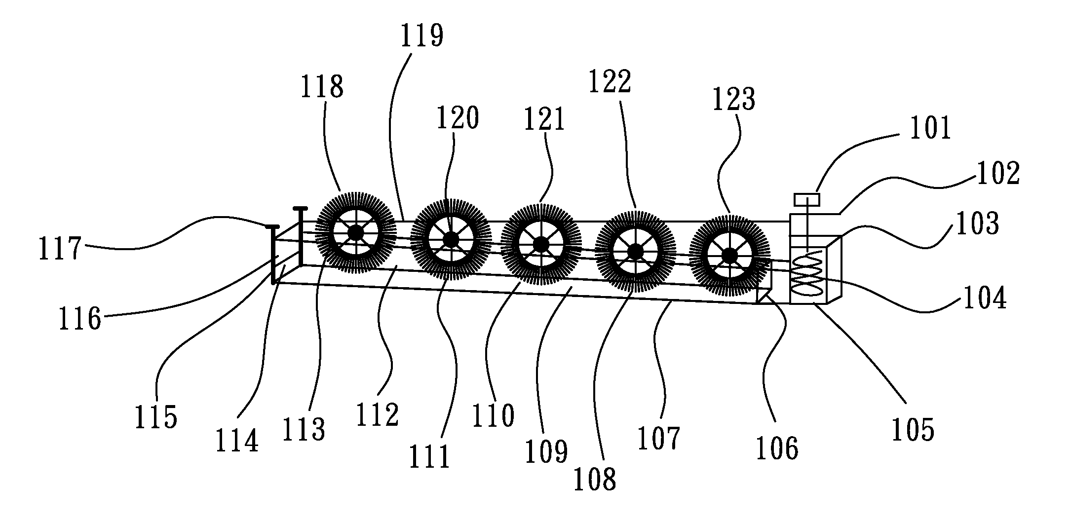
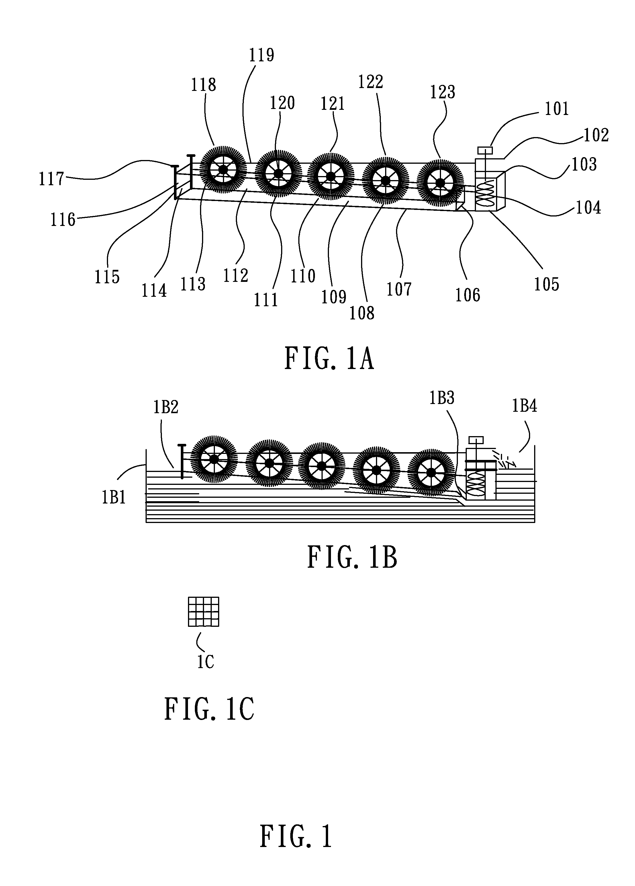
[0042]FIG. 1 shows a hydroelectric installation in accordance with the present invention, and the fundamental structure technical features of the present invention comprises: 1. a drain device includes powered water pumps and power supply switch control equipments, etc, such as the powered helical water pump 101 (as shown in FIG. 1A) which are disposed at a tail end of the flume; 2. flume containers are open-type flumes 105, 107; and 3. multiple power generating units 108, 123, 109, 122, 110, 121, 111, 120, 112, 118 and various facilities with respect to the above respective devices.

[0043]The water pump 101 has a motor to drive the water pump 104 including a helical waterwheel, which is disposed in the flume 105 to discharge the water from the well of the flume 105 out of the flume 105 through the drainage pipe exit 102, and drive the water outside the flume 105 to continually flow into the well of the flume 105 through the flumes 107, 106 to drive the respective waterwheel power ge...

second embodiment

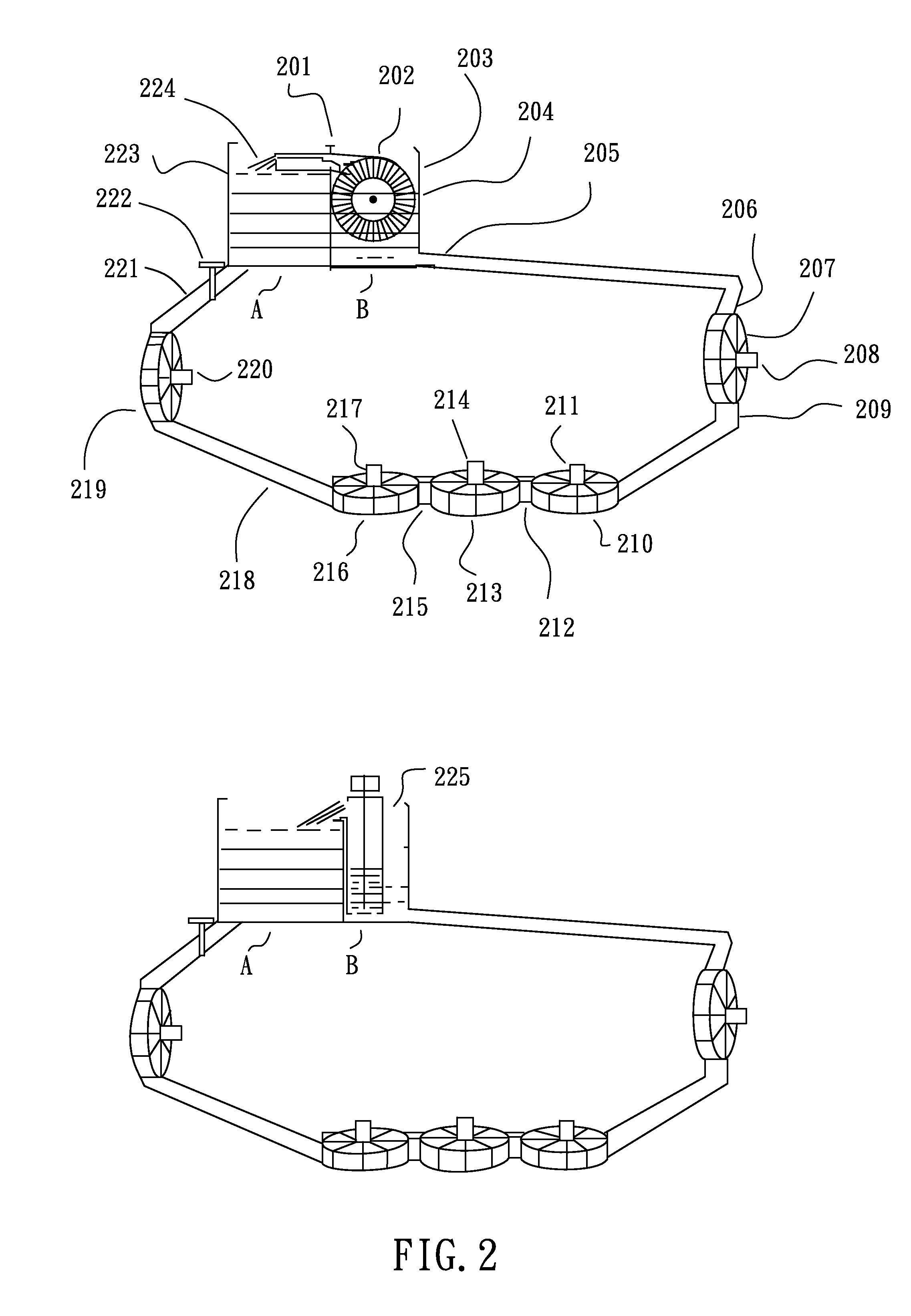
[0064]FIG. 2 illustrates a hydroelectric installation in accordance with the present invention. The main technical features of the present embodiment include: a liquid container 201 divided into two containers A and B by a divider, pipes 221, 205 employed to supply a proper liquid to the container B from the container A, the respective hydro-generators 220, 219, 217, 216, 214, 213, 211, 210, 208, 207 that are disposed on the pipe, a water pump 202 disposed in the container B and its power switch, etc. The containers and water pipes in the present embodiment can be made of metal or other various proper materials such as plastic, concrete, etc. The operation steps of the hydroelectric installation in the present embodiment can be operated in two methods: a.: firstly, closing the drainage valve 222 on the pipe of the container A; and then filling water into the container A until the water reaches the water level 223; after that, opening the drainage valve 222 to make the water in the c...

third embodiment

[0068]Referring to FIG. 4 a hydroelectric installation in accordance with the present invention comprises a liquid drainage passage defined by a water tank 405, a drainage passage 406, a flume outlet 410, etc, a suction pipe 401 and a suction inlet 402 of an electric water pump that is installed on a riverbed or in the sea, and plural hydro-generators 407, 408, 409 that are installed on an oblique flume. Further, the reference number 403 in FIG. 4 represents the water level 403 of the suction pipe. The operation method of the hydroelectric installation in the present embodiment comprises the steps of: firstly, actuating a water pump 404 by means of external power to pump water from the river or sea into the drainage passage 406 of the container through the suction inlet 402, and then the water will flow along the drainage passage 406 downwards and finally out of the flume outlet 410 into the desired positions such as reservoir 411, man-made channel or natural channel 412, etch. Whil...


PUM


Abstract

A device for utilizing water flow kinetic energy continuously comprises at least one water pump, at least one flume and plural hydro-generators. The water pump is employed to continuously supply water from a water supply to an upper head end of a flume, and then the water will naturally flow from the upper head end of the flume to a lower tail end to drive the plural hydro-generators disposed on the flume to generate power. The flume has a length larger than a distance between the water supply and an upper head end of the flume. The water is finally discharged to a desired position or back to the upper head end by a water pump disposed at the lower tail end of the flume.

Description

BACKGROUND OF THE INVENTION[0001]1. Field of the Invention[0002]The present invention relates to a device and a method for utilizing water flow kinetic energy continuously.[0003]2. Description of the Prior Art[0004]Commonly, all the existing water power stations generate power by converting potential energy into kinetic energy. The convention method for establishing a relatively high and large reservoir wastes lots of time, material resource and labor in cutting off water flow, and destroying villages and forest, etc to build dams. In addition, because of natural disasters such as earthquake or human factors, the dam is likely to break to cause immeasurable loss. Once no enough water supplies to the reservoir from the upstream or no ample rainwater falls into the reservoir, the water storage tanks of these water power stations are unable to generate power to the power consumers, thus directly affecting people's work and normal life.[0005]In addition, all the conventional hydroelectr...

Claims


Application Information

Patent Timeline
Patent Type & Authority Applications(United States)
IPC IPC(8): F03B13/08F03B17/04
CPCE02B9/00F03B17/005F03B17/063Y02E10/28F05B2240/93Y02E10/22F05B2240/40Y02E10/20Y02E10/30
Inventor LEUNG, KWONG-KEUNG
Owner LEUNG KWONG KEUNG
Why Eureka
Try Eureka