
Lighting controller

a technology of lighting controller and controller, which is applied in the direction of lighting apparatus, light sources, electric lighting sources, etc., can solve the problem of limited options for lighting system control

Inactive Publication Date: 2010-08-19
C P ELECTRONICS
View PDF7 Cites 44 Cited by
  • Summary
  • Abstract
  • Description
  • Claims
  • Application Information

AI Technical Summary

Benefits of technology

[0004]The combination of a manually-operable dimmer and an occupancy sensor in a wall-mounted lighting controller provides the possibility of completely new modes of operation of the controller. For example, the controller can be arranged to raise the lighting level gradually to a desired level selected by the user when the occupancy sensor detects the presence of a person, rather than simply switching the lighting immediately to maximum brightness. This can prevent a user being blinded by the lighting as it is activated automatically.
[0005]The operation of the controller may be responsive to the current ambient lighting level. For example, the controller may be arranged to raise the output power slowly if the difference between the ambient level and the desired lighting level is large. In other words, if a room is dark, the controller may bring the lights up slowly when the occupancy sensor is triggered so as not to blind the occupant of the room, whereas in a room that is dimly lit, the controller may bring the lights up quickly when the occupancy sensor is triggered without blinding the occupant.
[0010]In embodiments of the invention, the controller may comprise a light which is configured to illuminate when the intensity of the light detected by the light sensor is below a predetermined threshold. The controller may include a light that is activated when the electrical power of the output is below a predetermined threshold. The light provides a way of locating the controller in the dark, but ensures that power is not wasted when the lighting level is high enough to see the controller.
[0012]It will be seen that embodiments of the invention provide a highly flexible control device, capable of altering its output in response to the presence of a person, ambient light levels, the time of day or the time since some input, as well as manual inputs from the user.
[0014]The dimmer may be any suitable device, but in the preferred arrangement the dimmer controls the output power of the controller by limiting the amount of time within the alternating current cycle that current passes to the load.

Problems solved by technology

The systems illustrated in these documents provide users with a few limited options for the control of lighting systems.

Method used


Image

  • Lighting controller
  • Lighting controller
  • Lighting controller

Examples


Embodiment Construction

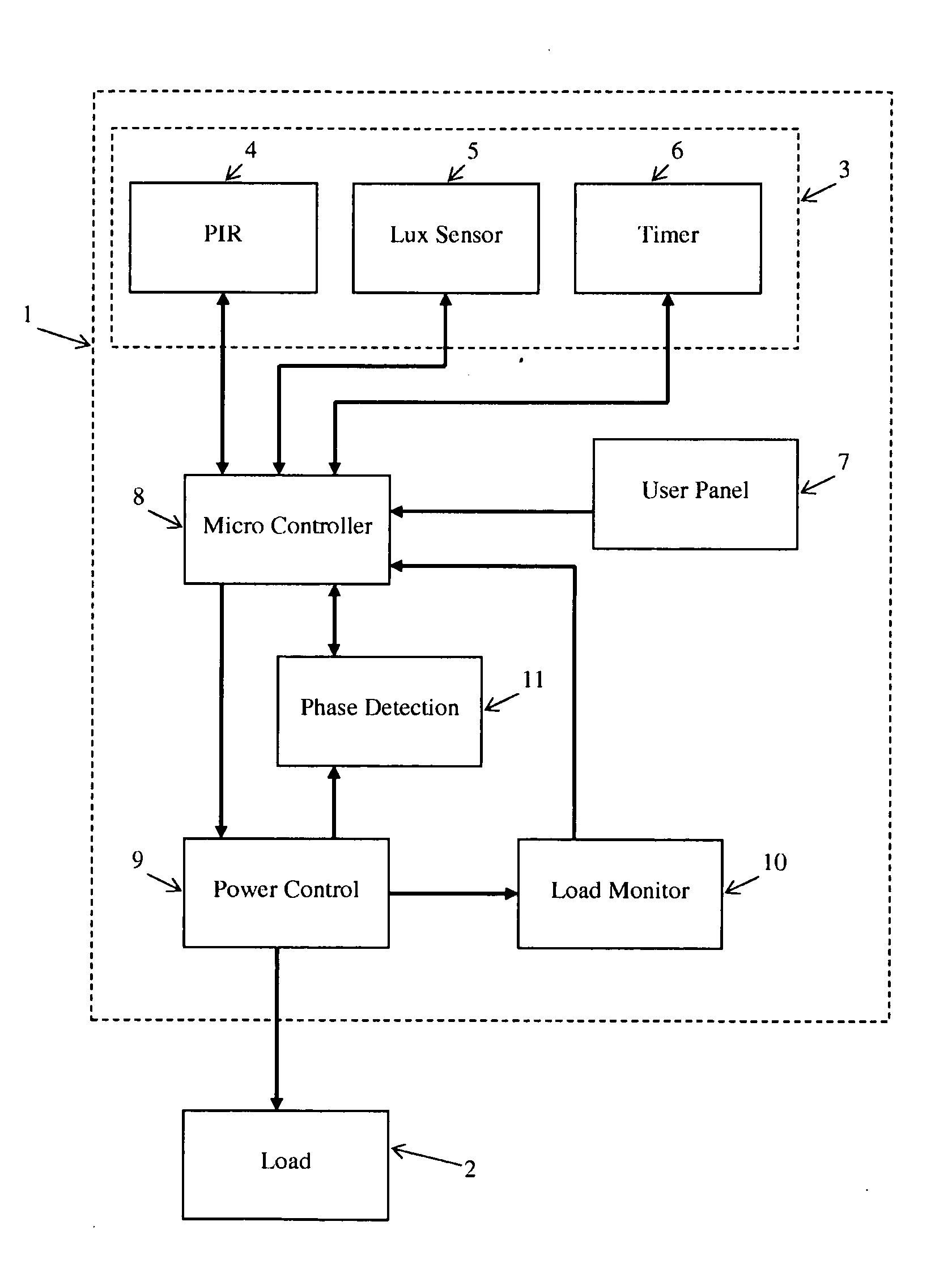
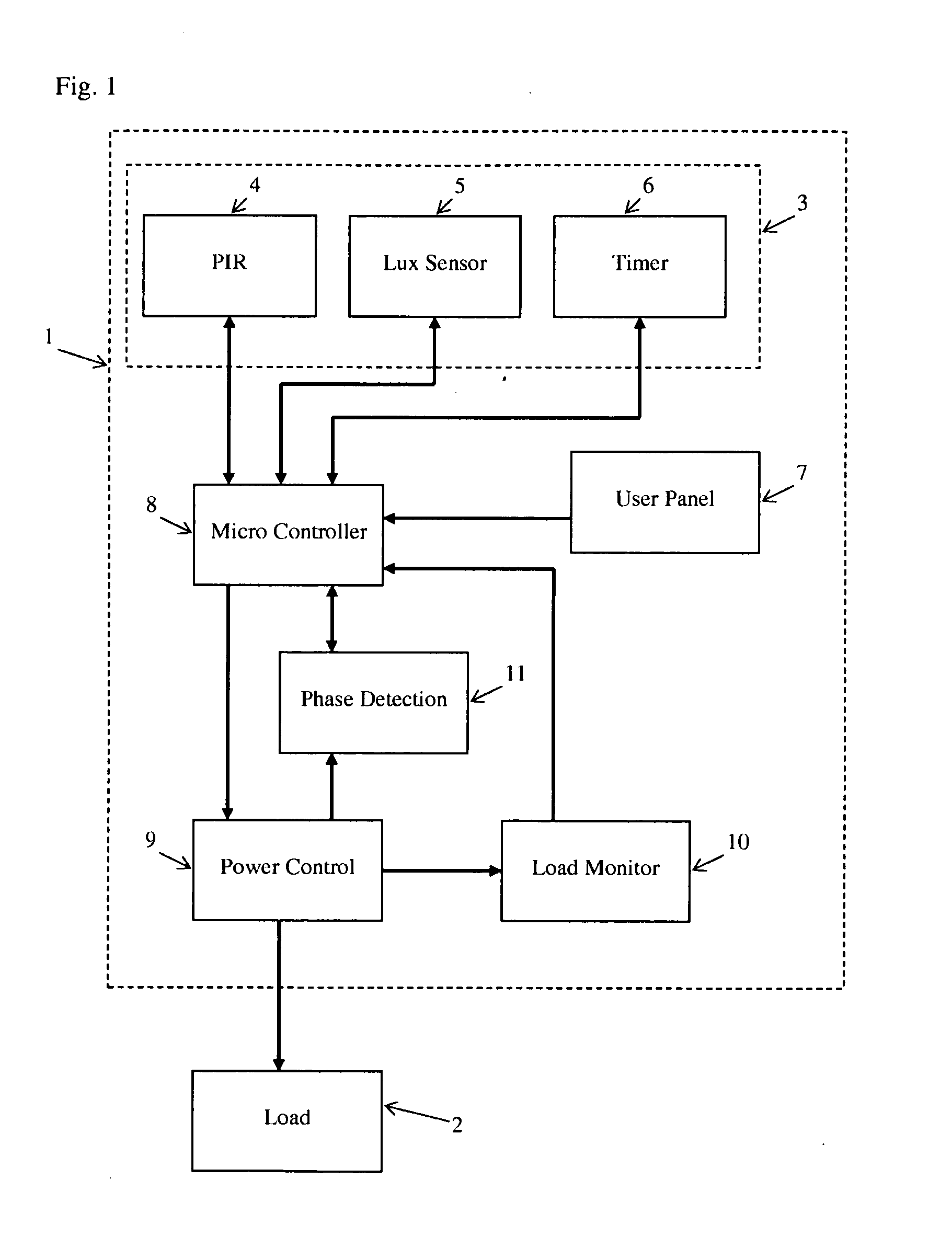
[0022]FIG. 1 shows a diagram of a lighting controller 1 according to the invention connected to a load in the form of a lamp 2. The lighting controller 1 comprises a plurality of sensing modules 3. A first sensing module is a passive infra red (PIR) occupancy sensor 4 which can detect the presence of a moving hot body such as a person. A second sensing module is a light (Lux) sensor 5 which measures the intensity of light falling on the lighting controller 1. The third sensing module is a timer 6. The lighting controller 1 also has a user panel 7 on which are provide manual controls for the user. Each of the sensing modules 3 and the user panel 7 are connected to a microcontroller 8.

[0023]The microcontroller 8 is in turn connected to a power control module 9. The power control module 9 operates as a dimmer to control the power supplied to the lamp 2. Feedback to the microcontroller 8 on the power control module 9 is provided by a load monitor 10 and a phase detection module 11.

[0024...


PUM


Abstract

A device for replacing conventional wall mounted light switches in situ comprises a dimmer (1) and an occupancy sensor (4). These are arranged such that the electrical power of at least one output (2) can be varied manually and in response to signals generated by the occupancy sensor.

Description

FIELD OF THE INVENTION[0001]This invention relates to a lighting controller.BACKGROUND TO THE INVENTION[0002]A variety of devices are already known for controlling the lighting systems that are ubiquitous in practically all human habitations. US 2006 / 125624 relates to Passive Infra Red (PIR) motion sensors for automatically controlling the lights in a room. U.S. Pat. No. 4,151,426 discloses a security device that is intended to turn electrical appliances on and off automatically over a period of time in order to create the illusion of occupancy. The systems illustrated in these documents provide users with a few limited options for the control of lighting systems. However, it would be desirable to provide a lighting controller that provides a user with new possibilities for lighting control.SUMMARY OF THE INVENTION[0003]This invention provides a lighting controller suitable for replacing a conventional wall-mounted light switch. The controller comprises a dimmer arranged to vary the...

Claims


Application Information

Patent Timeline
IPC IPC(8): H05B37/02
CPCH05B41/36H05B37/02H05B47/115H05B47/17H05B47/13H05B47/11Y02B20/40H05B35/00H05B39/041H05B47/105
Inventor MANS, PAUL
Owner C P ELECTRONICS
Learn More