Multispectral imaging device with array of microlenses

a multi-spectral imaging and array technology, applied in the field of multi-spectral imaging devices, can solve the problems of difficult to envisage providing unsuitable for identifying variations in optical transmission, and difficult to achieve a large number of filters, so as to reduce the efficiency of the microlenses, increase the light flux in the photosensitive zone by 50%, and preserve the optical function of the microlenses

Active Publication Date: 2021-10-12
SILIOS TECH
View PDF9 Cites 1 Cited by
  • Summary
  • Abstract
  • Description
  • Claims
  • Application Information

AI Technical Summary

Benefits of technology

[0031]It is advantageous to arrange the filters above the microlenses in order to avoid problems associated with the angle of incidence on the filters.
[0033]Concerning fabrication yield, the device of the invention presents an undeniable advantage.
[0035]Furthermore, there is great flexibility in the configuration selected for the filter module and the detector. It is possible to adapt the filtering to a large number of detectors in order to enhance a particular characteristic of the imager: resolution, sensitivity, noise, . . . .
[0038]A first advantage of this solution lies in conserving the optical function of the microlenses, thereby increasing the light flux in the photosensitive zone by 50%. The presence of adhesive between the filter module and the microlenses reduces the efficiency of the microlenses considerably since the adhesive has a refractive index close to that of the lenses.
[0048]The advantage of adopting a filter of broad spectral band is that it gives a photometric reference on the image. The level of light flux integrated in the spectral band is equivalent to the flux contained in “color” bands. This serves to avoid blinding pixels that are adjacent to the panchromatic pixels.

Problems solved by technology

Furthermore, possibilities of miniaturization in this configuration are also very limited and it is difficult to envisage providing a large number of filters.
Nevertheless, they assume that the item for analysis is an indissociable entity, i.e. that is not resolved in three dimensions, and they are not suitable for identifying variations in optical transmission or reflection within the item itself.
Specifically, it is not possible to envisage depositing the matrix of filters on the microlenses since the topology of the microlenses is very marked.
Furthermore, the microlenses are made of resin so that it can be difficult to make an inorganic filter on an organic material.
Unfortunately, the aperture angle of the incident beam on the filters is large when they are arranged under microlenses.

Method used


Image

  • Multispectral imaging device with array of microlenses
  • Multispectral imaging device with array of microlenses
  • Multispectral imaging device with array of microlenses

Examples


Embodiment Construction

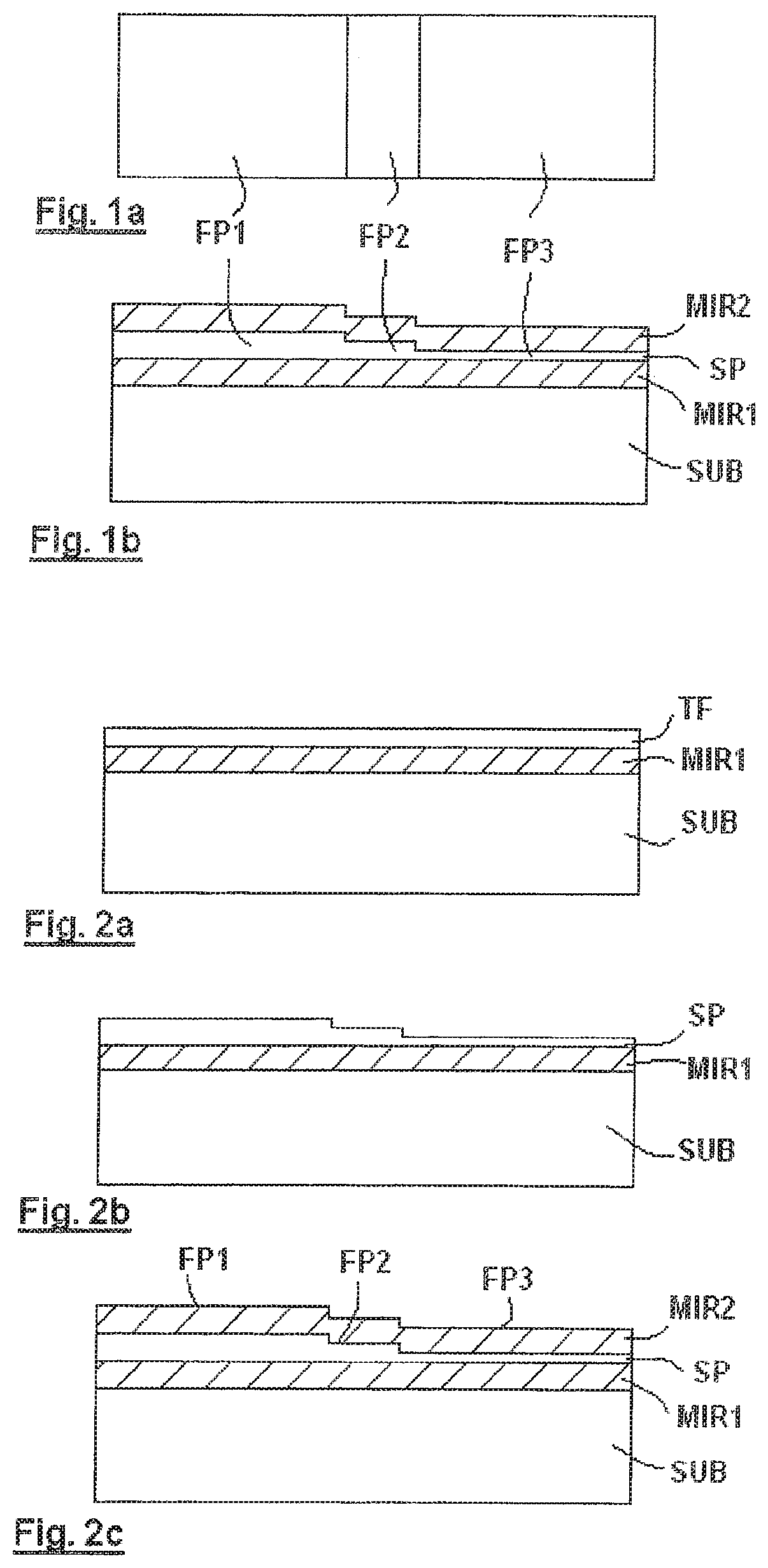
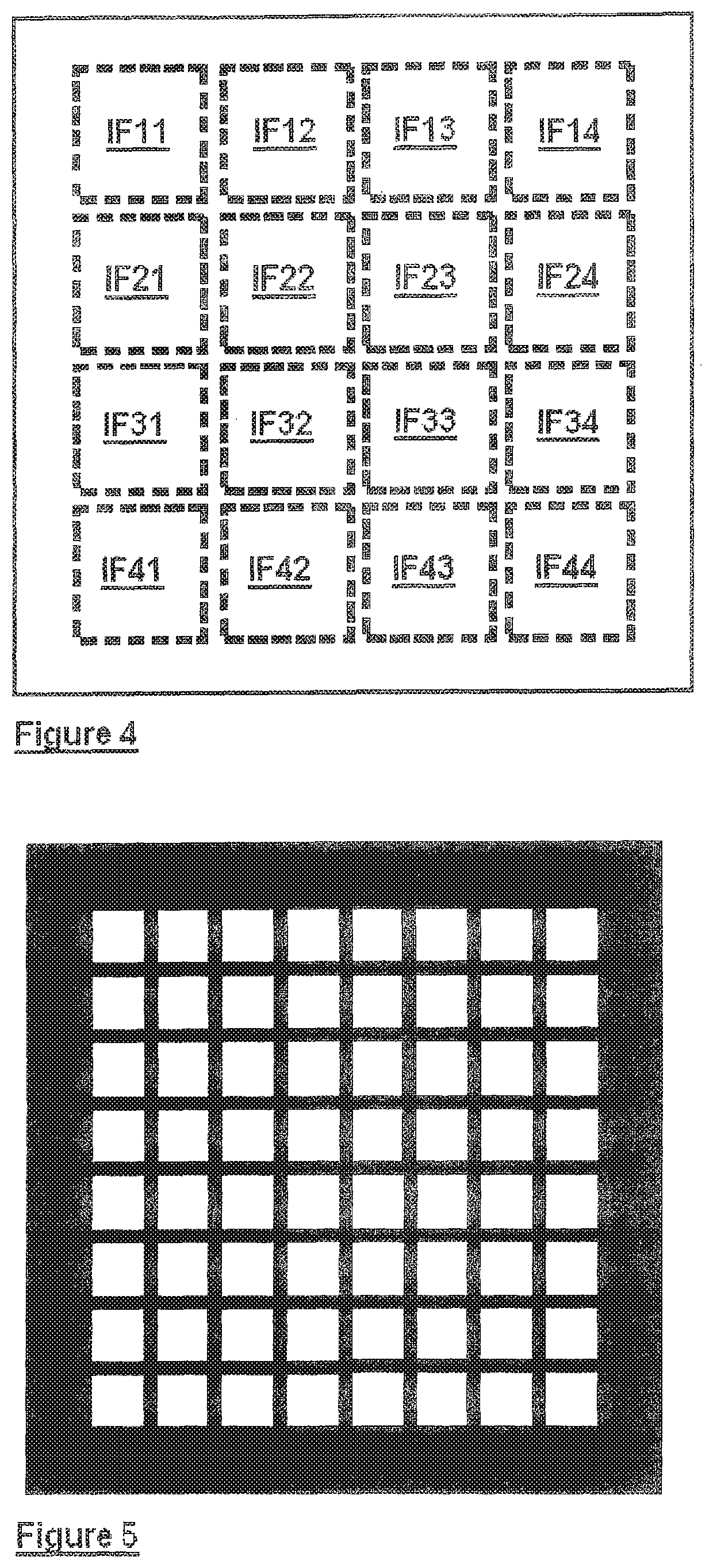
[0060]The description begins with a filter module having a plurality of generally identical filter cells.

[0061]With reference to FIGS. 1a and 1b, a filter cell comprises three Fabry-Perot type interference filters FP1, FP2, and FP3 in successive alignment so as to form a strip.

[0062]The cell is constituted by a stack on a substrate SUB, e.g. made of glass or silica, the stack comprising a first mirror MIR1, a spacer SP, and a second mirror MIR2.

[0063]The spacer SP, which defines the center wavelength of each filter, is thus constant for a given filter, and varies from one filter to another. Its profile is staircase-shaped since each filter has a surface that is substantially rectangular.

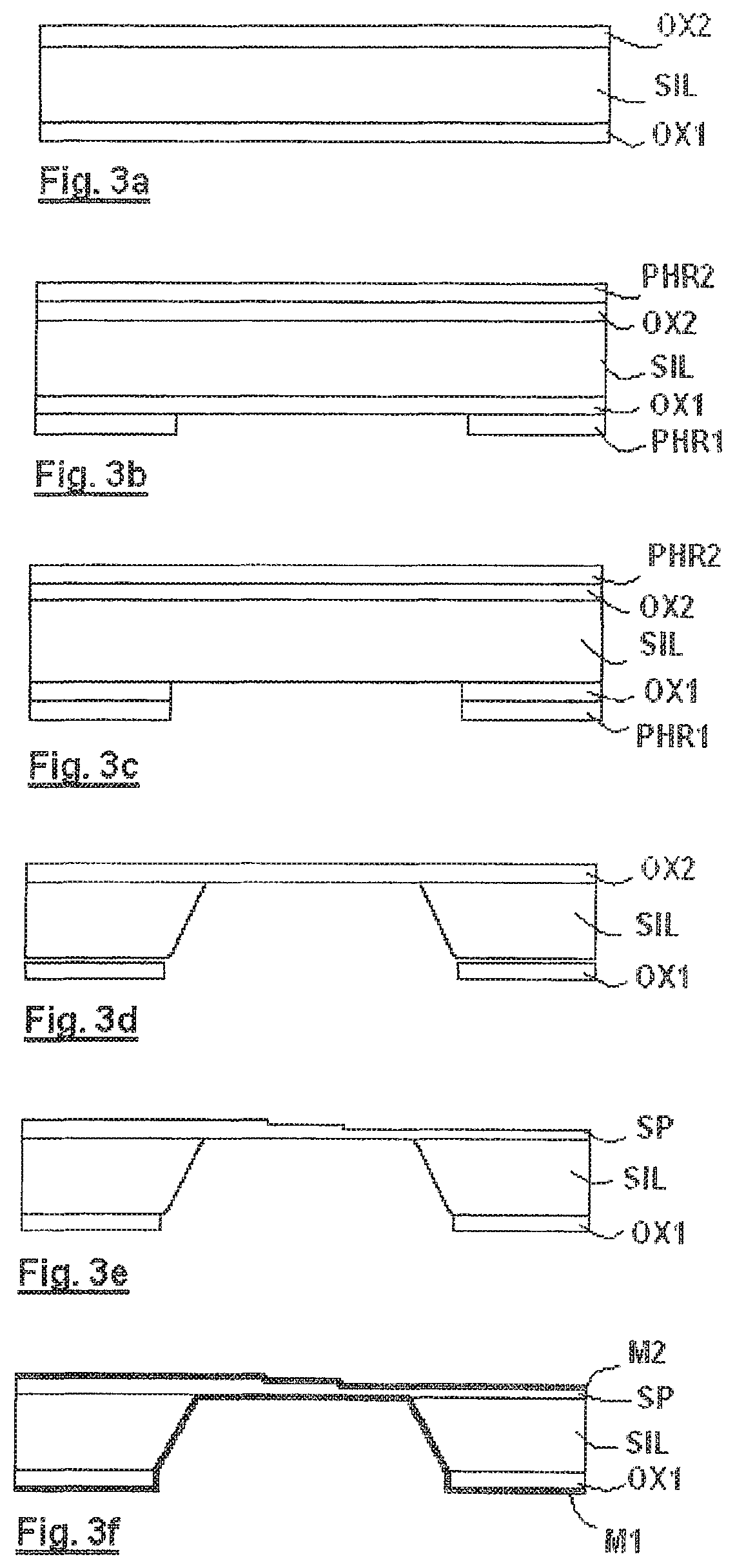
[0064]A first method of making the filter module in thin film technology is given by way of example.

[0065]With reference to FIG. 2a, the first mirror MIR1 is initially deposited on the substrate SUB followed by one or more dielectric layers TF for defining the spacer SP. The mirror is either metallic...


PUM

PropertyMeasurementUnit
optical thicknessaaaaaaaaaa
wavelengthaaaaaaaaaa
sizeaaaaaaaaaa

Abstract

The invention relates to a multispectral imaging device including: a photosensitive detector DET made up of a matrix of pixels; an array of microlenses ML1, ML2, ML3 reproducing the matrix of pixels; and a filter module MF formed by a matrix of individual filters λ1, λ2, λ3 reproducing the matrix of pixels. The device is remarkable in that the array of microlenses is arranged directly in contact with the detector DET, and the filter module MF is made on a substrate SS that is put into contact with the array of microlenses.

Description

CROSS REFERENCE TO RELATED APPLICATIONS[0001]This Application is a National Stage of International Application No. PCT / FR2017 / 000076 filed Apr. 27, 2017, claiming priority based on French Patent Application No. 16 / 00716 filed Apr. 29, 2016.BACKGROUND OF THE INVENTION[0002]The present invention relates to a multispectral imaging device.[0003]Spectrometric analysis seeks in particular to find the chemical constituents in the composition of a solid, liquid, or gaseous medium. It involves recording the absorption spectrum of the medium in reflection or in transmission. The light that has interacted with the medium is absorbed in certain wavelength bands. This selective absorption gives a signature for some or all of the constituents of the medium. The wavelength range of the spectrum to be measured may lie in the ultraviolet range and / or the visible range and / or the (near, medium, far) infrared range.[0004]This analysis is commonly performed using a spectrometer.[0005]Certain spectromet...

Claims


Application Information

Patent Timeline
Patent Type & Authority Patents(United States)
IPC IPC(8): G01J3/02G01J3/28G02B3/00G02B5/20G02B19/00G02B5/28
CPCG01J3/0229G01J3/0208G01J3/0213G01J3/2803G01J3/2823G02B3/0056G02B5/201G02B5/284G02B19/0076G01J2003/2806G01J2003/2813G01J2003/2826
Inventor TISSERAND, STEPHANEROUX, LAURENTHUBERT, MARCSAUGET, VINCENTFAIOLA, AURELIEN
Owner SILIOS TECH
Why Eureka
Try Eureka