Lidar system

a lidar system and detector technology, applied in the field of lidar systems, can solve the problems of excessive light being cast back onto the detector, the lidar system may be blinded, and the risk of optical crosstalk between individual pixels of the detector

Active Publication Date: 2018-12-06
ROBERT BOSCH GMBH
View PDF0 Cites 1 Cited by
  • Summary
  • Abstract
  • Description
  • Claims
  • Application Information

AI Technical Summary

Benefits of technology

[0018]Finally, the present invention also relates to a vehicle that comprises a lidar system as previously described. The lidar system makes it possible for the vehicle securely and reliably to detect and measure a surroundings, the lidar system being at the same time protected against interference from other lidar systems and / or against being blinded by incident outside light. The lidar system is thus optimally suited for use in a vehicle since such interfering lights often occur in the surroundings of vehicles. On account of the lidar system, the vehicle is thus able to detect the surroundings securely and reliably.

Problems solved by technology

In conventional lidar systems, in particular as previously described, there is, however, the risk of optical crosstalk between individual pixels of the detector.
Blooming is particularly problematic in spatially resolved lidar systems since the position of the object to be detected can only be measured at a great error tolerance.
In addition, the lidar system may be blinded in that an excessive quantity of light is cast back onto the detector.
If light is cast by the lidar system onto a target that is located very near the output face of the lidar system, the detector is excessively irradiated if the emitted beam power is adjusted to the maximum range of the lidar system and a weakly reflecting target.
This is particularly disadvantageous in use in motor vehicles when the target is a retroreflector, for example a license plate of a preceding vehicle.
The described high beam power that strikes the detector results in optical crosstalk and thus in the loss of the resolution capacity of the sensor.
Consequently, there is the risk that targets are detected in wrong locations.
This is particularly harmful if SPAD detectors are used that have a long dead time, in which they are blind due to system-related factors, which means that they are unable to perform further measurements.
Conventional lidar systems would be blinded in this case and would no longer be able to measure correctly.
This means that laser light that was emitted and that strikes a nearby target has a short propagation time.
It is thus not possible for the lidar system to be disturbed by outside light, for example by sunlight or by other lidar systems.
If the quantity of light striking the detector is reflected by a real object near the sensor, the additional sensor is blinded.

Method used


Image

  • Lidar system
  • Lidar system
  • Lidar system

Examples


Embodiment Construction

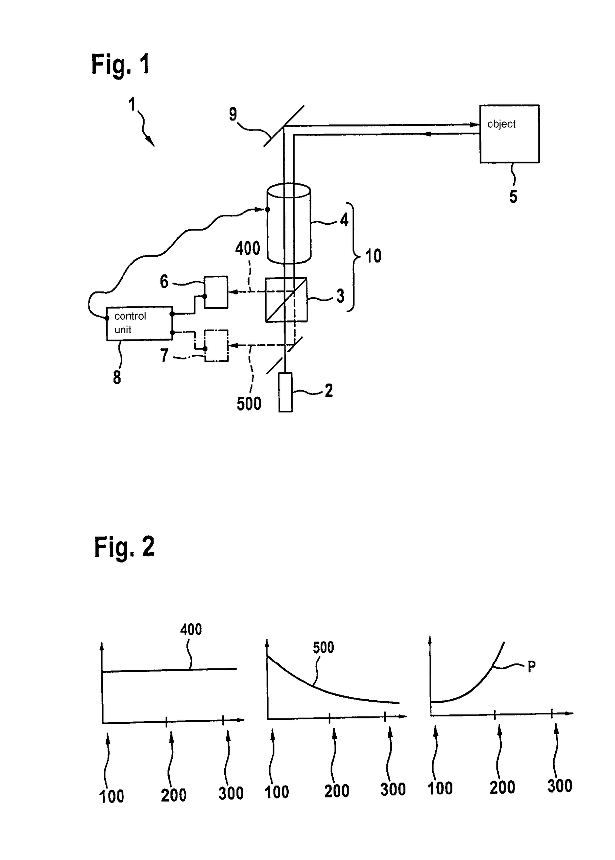
[0024]FIG. 1 shows schematically a lidar system according to an exemplary embodiment of the present invention. Lidar system 1 comprises a laser light source 2 and a light modulator unit 10. In the exemplary embodiment shown, the light modulator unit 10 is implemented by a beam splitter 3 and a Pockels cell 4. Laser light source 2 is used to emit a laser light. The laser light passes through the components of beam splitter 3 and Pockels cell 4, as a result of which the laser light obtains a predefined polarization. Subsequently, the laser light passes through a deflecting device 9 and is deflected by deflecting device 9. Deflecting device 9 is in particular designed to be movable and allows for the laser light to be deflected onto different areas in a surroundings of lidar system 1.

[0025]The laser light emitted by lidar system 1 is reflected by an object 5 in the surroundings of lidar system 1. Lidar system 1 is developed to be in particular coaxial, as a result of which the reflecte...


PUM


Abstract

A lidar system comprising a laser light source for emitting laser light, a light modulator unit, and a detector, the laser light emitted by the laser light source and reflected by an object being directed first through the light modulator unit and thereupon onto the detector, and the light modulator unit being designed to modify over time a light output that strikes the detector.

Description

CROSS REFERENCE[0001]The present application claims the benefit under 35 U.S.C. § 119 of German Patent Application No. DE 102017209259.9 filed on Jun. 1, 2017, which is expressly incorporated herein by reference in its entirety.BACKGROUND INFORMATION[0002]The present invention relates to a lidar system. The present invention also relates to a vehicle, comprising such a lidar system.[0003]Conventional lidar scanners generally either have a macromirror or a rotating aggregate unit. The design of the scanners is usually biaxial, which means that a transmission path and a receiving path have separate transmission routes and receiving routes. In coaxial scanners, transmission paths and receiving paths are largely identical.[0004]A lidar system is described in U.S. Patent Application Pub. No. 2008 / 137058 A, for example. In this instance, a polarizing beam splitter is used as well as a quarter-wave plate. A laser light source emits light in a linear polarization direction, which passes thr...

Claims


Application Information

Patent Timeline
Patent Type & Authority Applications(United States)
IPC IPC(8): G01S7/486G01S7/499G01S7/481G01S17/931
CPCG01S7/4868G01S7/499G01S7/4812G01S17/936G01S7/489G01S17/931
Inventor HOLLECZEK, ANNEMARIESCHWARZ, HANS-JOCHEN
Owner ROBERT BOSCH GMBH
Why Eureka
Try Eureka