LED lamp

a technology of led lamps and diodes, which is applied in the field of led lamps, can solve the problems of unsatisfactory spatial distribution of led lamps and inability to provide a larger illumination area

Inactive Publication Date: 2010-08-19
FU ZHUN PRECISION IND SHENZHEN +1
View PDF20 Cites 11 Cited by
  • Summary
  • Abstract
  • Description
  • Claims
  • Application Information

AI Technical Summary

Problems solved by technology

Since a lighting angle of the LEDs is generally restricted in a narrow range, light of the LED lamp i

Method used


Image

  • LED lamp
  • LED lamp
  • LED lamp

Examples


Embodiment Construction

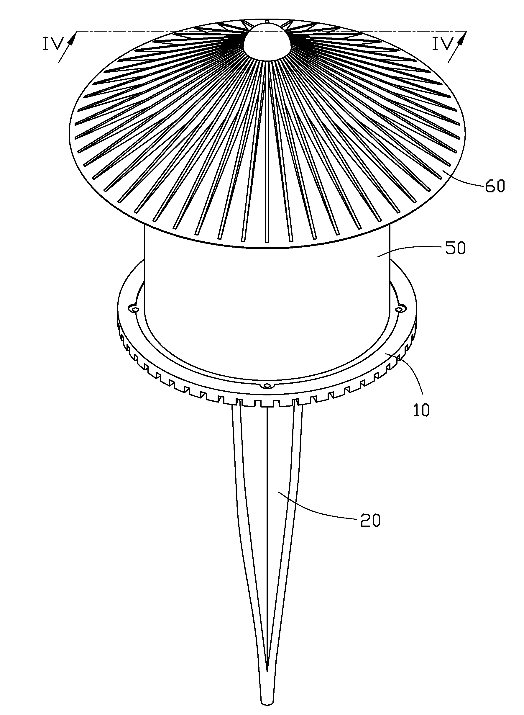
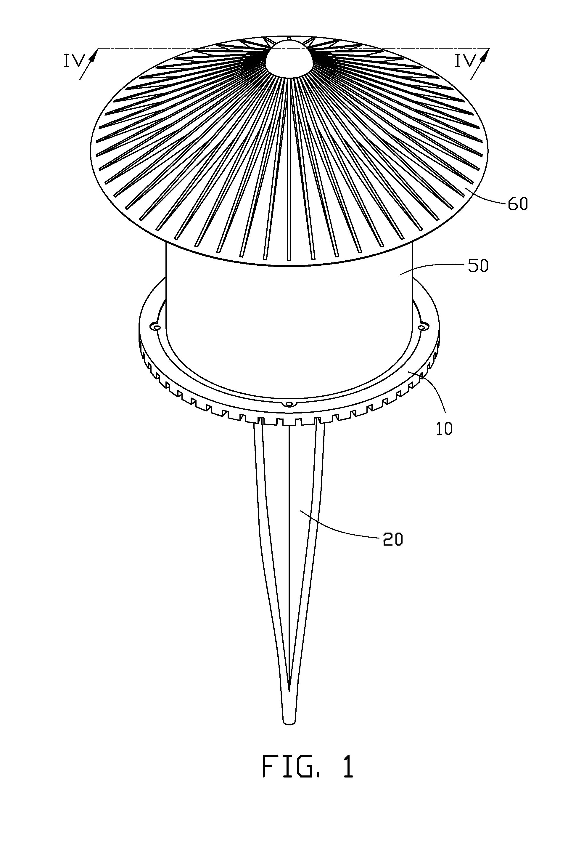
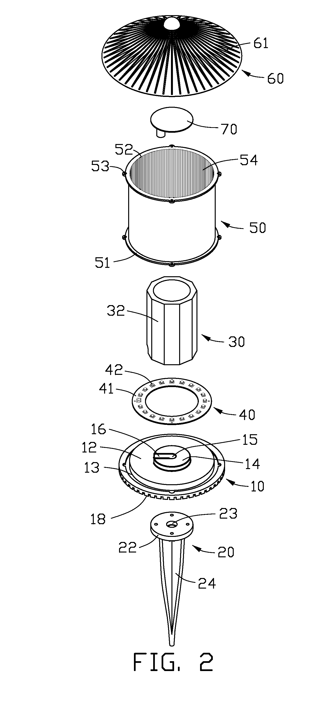
[0012]Referring to FIGS. 1-2, an LED lamp in accordance with an embodiment comprises a base 10, an inserting post 20 connecting the base 10, a reflector 30 mounted on the base 10, an LED module 40 attached to the base 10 and surrounding the reflector 30, an envelope 50 mounted on the base 10 and enclosing the LED module 40 and the reflector 30 therein, and a shield 60 secured on the envelope 50 and covering the reflector 30 and the envelope 50. A rectifier 70 is located below the shield 60 and engages with the shield 60 for electronically connecting the LED module 40.

[0013]Referring to FIGS. 2-3, the base 10 is made of heat conductive material such as aluminum or the like and is substantially a round plate. A first round platform 12 protrudes from a top surface of the base 10. A groove 13 surrounds the first platform 12 for receiving a bottom end of the envelope 50 therein. A second round platform 14 protrudes upwardly from the first platform 12. The first and second platforms 12, 1...


PUM


Abstract

An LED lamp includes a base, a reflector arranged on a top of the base, an LED module attached to the top of the base and surrounding the reflector, an envelope arranged on the top of the base and enclosing the LED module and the reflector, a shield secured on the envelope and covering the reflector and the LED module, and an inserting post fixed on a bottom of the base for facilitating inserting into a foundation to secure the LED lamp thereon. A bottom surface of the shield is coated with a reflecting coating for reflecting light emitted by the LED module.

Description

BACKGROUND[0001]1. Technical Field[0002]The present disclosure relates to LED (light emitting diode) lamps for lighting purpose and, more particularly, to an improved LED lamp having a novel structure for use in the outdoors.[0003]2. Description of Related Art[0004]An LED lamp is a type of solid-state lighting that utilizes LEDs as a source of illumination. The LED has an advantage that it is resistant to shock, and has an almost eternal lifetime under a specific condition; thus, the LED lamp is intended to be a cost-effective yet high quality replacement for incandescent and fluorescent lamps.[0005]Known implementations of LED modules in an LED lamp make use of a plurality of individual LEDs to generate light that is sufficient. Since a lighting angle of the LEDs is generally restricted in a narrow range, light of the LED lamp is of unsatisfactory spatial distribution, whereby a more larger illumination area can not be provided.[0006]What is needed, therefore, is an improved LED la...

Claims


Application Information

Patent Timeline
IPC IPC(8): F21V7/00F21S13/10
CPCF21S8/081F21V7/0008F21V7/0025F21Y2101/02F21V21/0824F21V29/004F21W2131/109F21V13/04F21Y2115/10F21V29/77
Inventor LUO, QIANGYU, GUANG
Owner FU ZHUN PRECISION IND SHENZHEN
Why Eureka
Try Eureka