

Electrical connector having grounding terminal having tail portion interconnected to metallic shell surrounding the connector
- Summary
- Abstract
- Description
- Claims
- Application Information
AI Technical Summary
Benefits of technology
Problems solved by technology
Method used
Image

Examples
Embodiment Construction
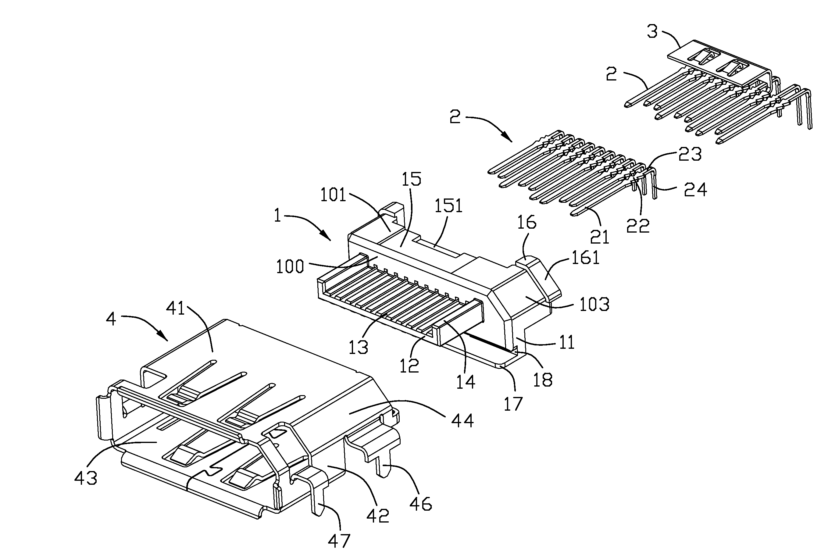
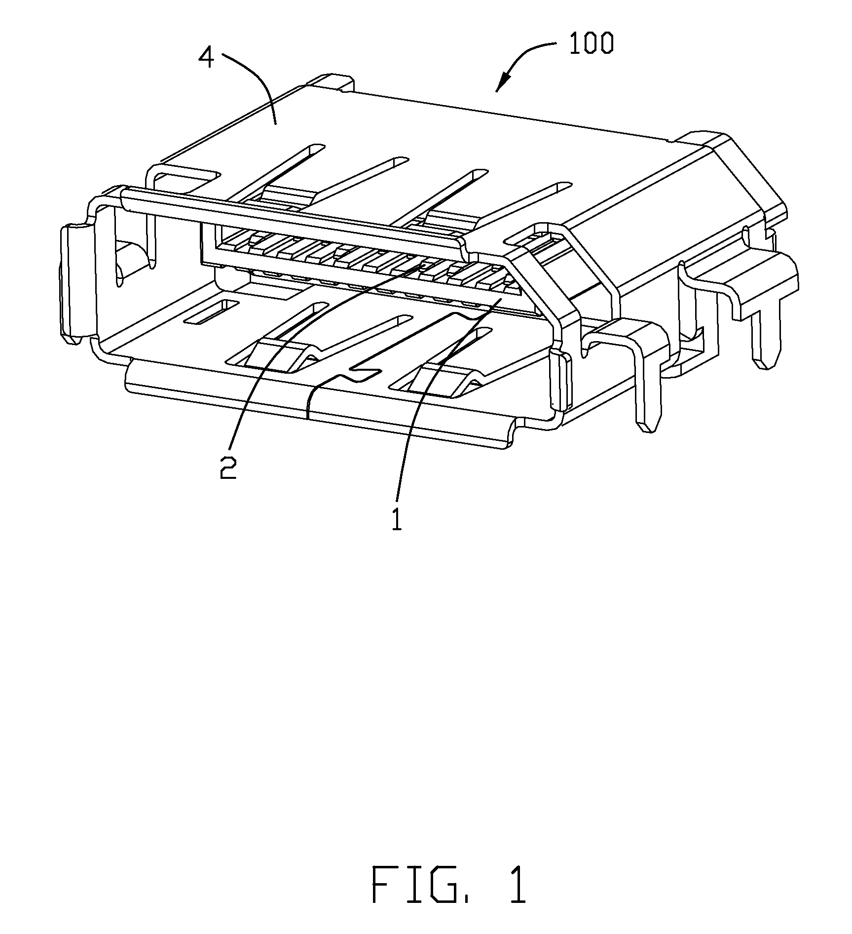
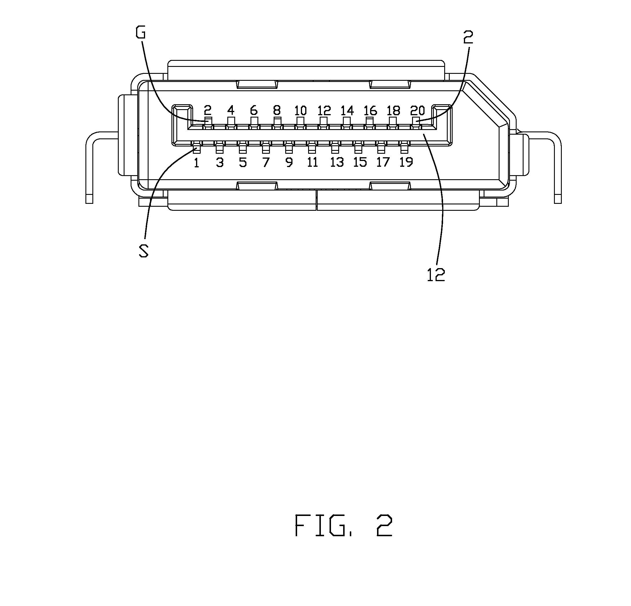
[0019]Reference will now be made to the drawing figures to describe a preferred embodiment of the present invention in detail. Referring to FIGS. 1-3, an electrical connector 100 according to the preferred embodiment of the present invention is provided and comprises an insulative housing 1 (hereinafter, simply referred to as “housing”), a plurality of conductive terminals 2 (differential signal transmission terminals and grounding terminals) mounted on the housing 1, a grounding plate 3 contacting with the conductive terminals 2, and a metallic shell 4 shielding the outside of the housing 1. The conductive terminals 2 are arranged into differential pair arrangement, i.e. a pair of signal terminals with one grounding terminal.
[0020]Referring to FIGS. 3 and 4, the housing 1 has a main body 11 and a tongue plate 12 that protrudes forward from a front surface 104 of said main body 11. A plurality of receiving grooves 13 are formed at a predetermined pitch on an upper surface and a lowe...
PUM
 Abstract
Description
Claims
Application Information