
Connection assembly for a golf club

a golf club and assembly technology, applied in the field of golf clubs, can solve the problem that the quick assembly shafts of the quick assembly of the golf club cannot be easily removed, and achieve the effect of limiting the opportunity for removal and replacemen

Active Publication Date: 2010-08-19
CALLAWAY GOLF CO
View PDF22 Cites 8 Cited by
  • Summary
  • Abstract
  • Description
  • Claims
  • Application Information

AI Technical Summary

Benefits of technology

[0013]The present invention provides an improved club head-shaft connection that temporarily couples standard, production golf club heads and shafts in a manner that does not adversely affect the playability of the resulting golf club. Because the quick sleeve and mechanical fastener connection is made of a strong engineered plastic, it is lightweight and does not add excessive weight, which would negatively impact the resulting golf club. The strong plastic material enables the present connection to oppose the high stresses that occur in the head-shaft connection during a club swing and upon impact with a golf ball. In addition, the present invention provides a consistent way of temporarily fixing a shaft to a club head, one that does not vary among different club head models. The present invention may further be applied to all wood-type golf clubs, including drivers and fairway woods.
[0014]The purpose of this invention is to enable easy installation of various shafts of interest into product-like heads to produce custom combinations of heads and shafts for trial by the golfing consumer.
[0015]Further, this invention seeks to minimize the meaningful mass, cost, appearance and structural differences between the bonded and otherwise assembled clubs and in the quick-fit shaft clubs.

Problems solved by technology

The one difference being that the rapid-production club quick assembly shafts can not be easily removed.

Method used


Image

  • Connection assembly for a golf club
  • Connection assembly for a golf club
  • Connection assembly for a golf club

Examples


Embodiment Construction

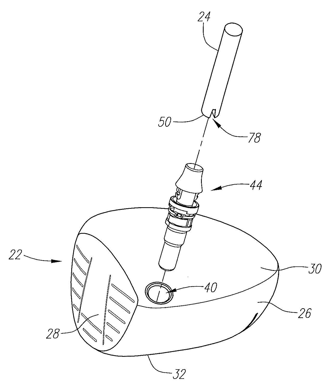
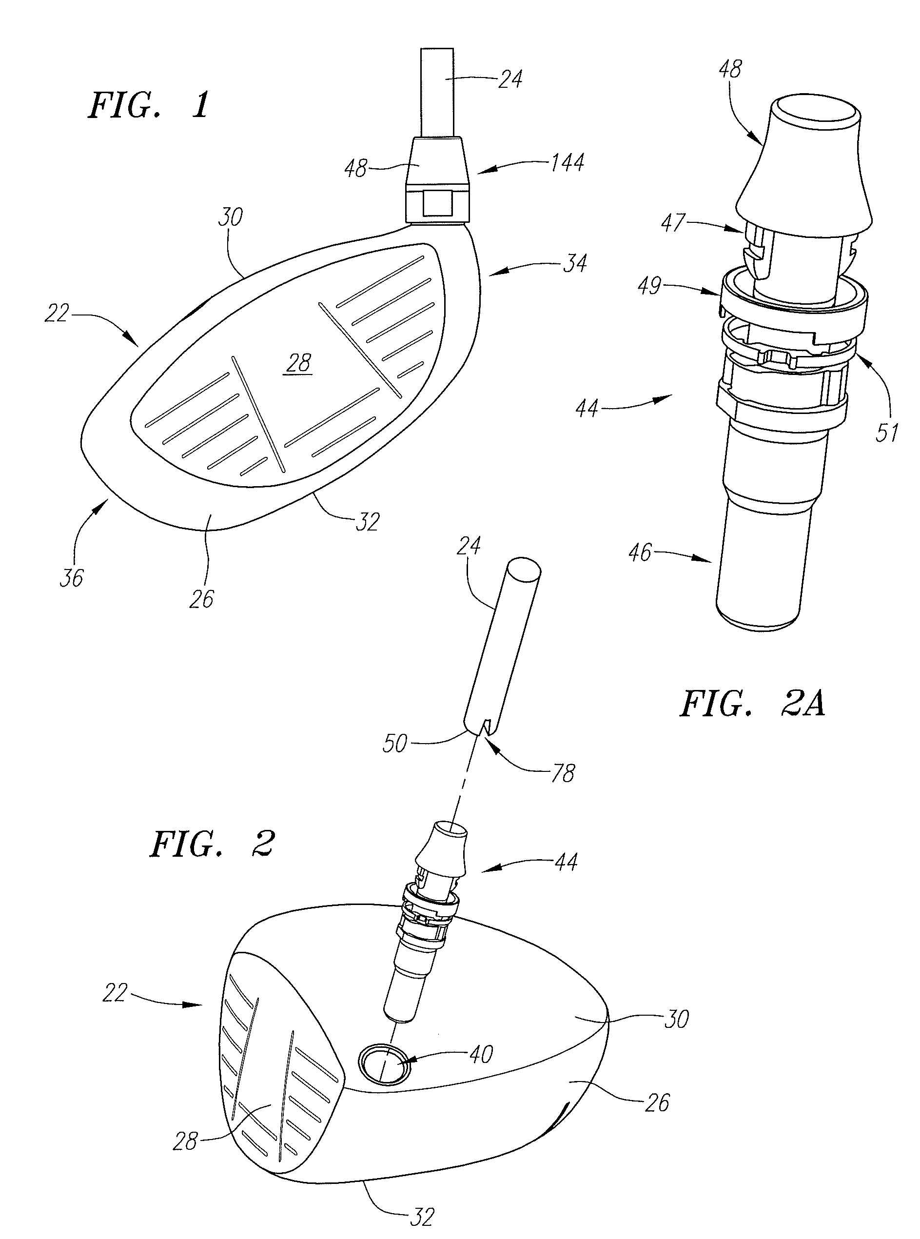
[0045]As shown in FIGS. 1 and 2, a golf club is generally designated 20. Golf club 20 has a club head 22 and a shaft 24 that is coupled to club head 22. Club head 22 is preferably a wood-type golf club head, such as a driver, a fairway wood, or even a hybrid iron-wood-type club. Club head 22 includes a body 26 having a striking face 28, a crown portion 30, a sole portion 32, a heel end 34 and a toe end 36. Striking face 28 generally extends along the front of club head 22 from heel end 34 to toe end 36.

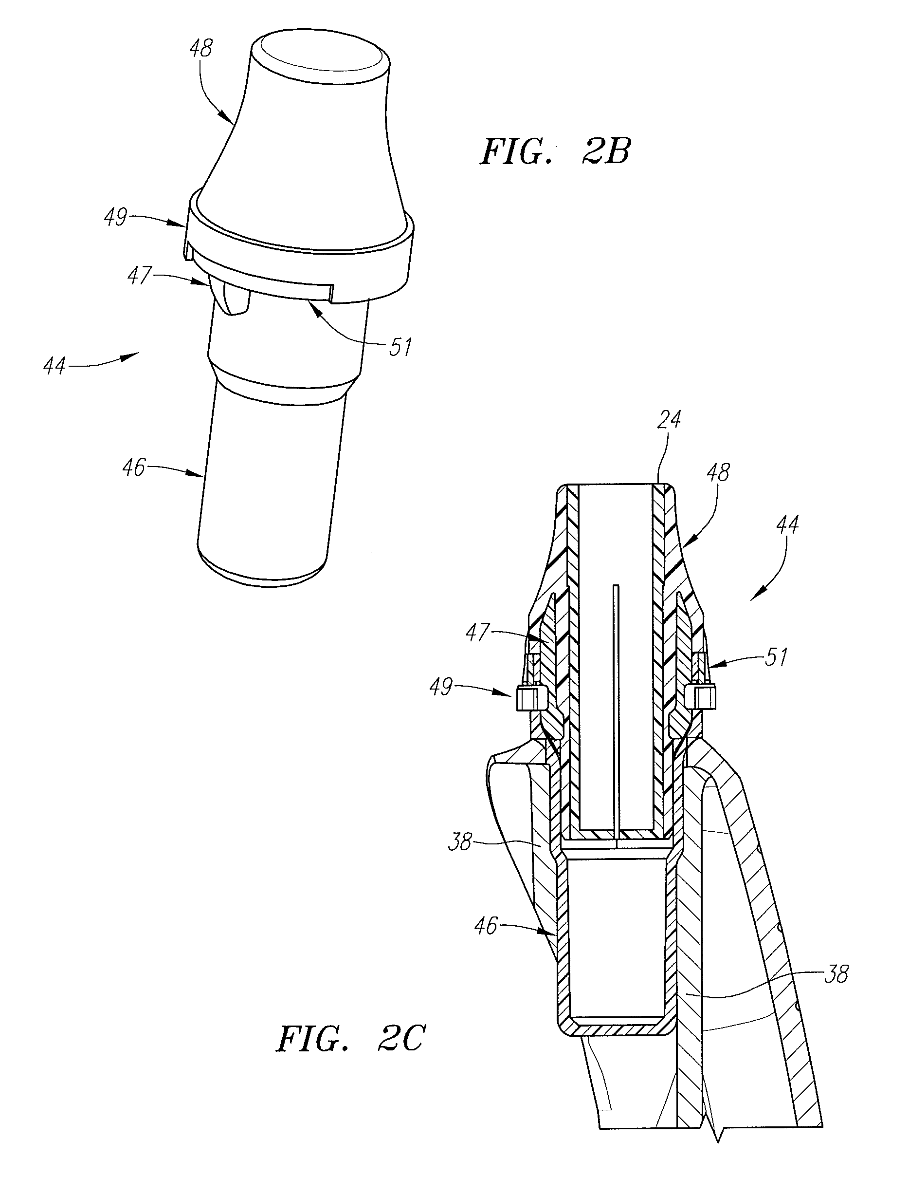
[0046]Body 26 is preferably composed of a metallic material, such as titanium, titanium alloy, stainless steel, or the like. Alternatively, body 26 may be composed of multiple materials, such as a titanium face cup attached to a carbon composite body, or a stainless steel body with a carbon composite crown. Body 26 preferably has a hollow interior and includes an internal hosel 38 (FIG. 3) for receiving shaft 24. Internal hosel 38 preferably extends through the entire body 26 with an ...


PUM


Abstract

A golf club including a club head and an interchangeable shaft is disclosed herein. A connection assembly (44) comprises a sleeve insert (47), a hosel sleeve (48), a hosel tube (46), a ring mechanism (48) and a guide ring (49).

Description

CROSS REFERENCES TO RELATED APPLICATIONS[0001]The Present application is a continuation-in-part application of U.S. patent application Ser. No. 12 / 046,597 filed on Mar. 12, 2008, which claims priority to U.S. Provisional Patent Application No. 60 / 894,415, filed on Mar. 12, 2007, now abandoned.STATEMENT REGARDING FEDERALLY SPONSORED RESEARCH OR DEVELOPMENT[0002]Not ApplicableBACKGROUND OF THE INVENTION[0003]1. Field of the Invention[0004]The present invention relates to a golf club having an improved connection for interchanging a shaft with a golf club head.[0005]2. Description of the Related Art[0006]In order to improve their game, golfers often customize their equipment to fit their particular swing. Golf equipment manufacturers have responded by increasing the variety of clubs available to golfers. For example, a particular model of a driver-type golf club may be offered in several different loft angles and lie angles to suit a particular golfer's needs. In addition, golfers can ...

Claims


Application Information

Patent Timeline
IPC IPC(8): A63B53/02A63B53/04
CPCA63B53/02A63B2210/50A63B2209/10A63B2209/00A63B60/00
Inventor GALLOWAY, J. ANDREW
Owner CALLAWAY GOLF CO
Learn More