
Electric power steering apparatus

a technology of electric power steering and steering shaft, which is applied in the direction of steering initiation, instrumentation, vessel construction, etc., can solve the problems of hysteresis imparted to the change of output mode, and achieve the effect of reducing the torque variation of the motor

Active Publication Date: 2010-08-19
JTEKT CORP
View PDF2 Cites 3 Cited by
  • Summary
  • Abstract
  • Description
  • Claims
  • Application Information

AI Technical Summary

Benefits of technology

[0006]In the electric power steering apparatus arranged as described above, the charge-discharge circuit is shifted from the first output mode to the second output mode on condition that the required electric power is equal to or higher than the first threshold value. Or conversely, charge-discharge circuit is shifted from the second output mode to the first output mode on condition that the required electric power is equal to or lower than the second threshold value that is lower than the first threshold value. Thus, hysteresis is imparted to the change of the output mode. Accordingly, the control for determining whether or not to use the auxiliary power supply can be prevented from hunting even if there are slight fluctuations of the steering assist force in the vicinity of either one of the thresholds.
[0008]In this case, a sharp voltage fluctuation associated with the transition from the mode in which the auxiliary power supply is used to the mode in which the auxiliary power supply is not used or vice versa is reduced so that the torque variations of the motor can be reduced.

Problems solved by technology

Thus, hysteresis is imparted to the change of the output mode.

Method used


Image

  • Electric power steering apparatus
  • Electric power steering apparatus
  • Electric power steering apparatus

Examples


Embodiment Construction

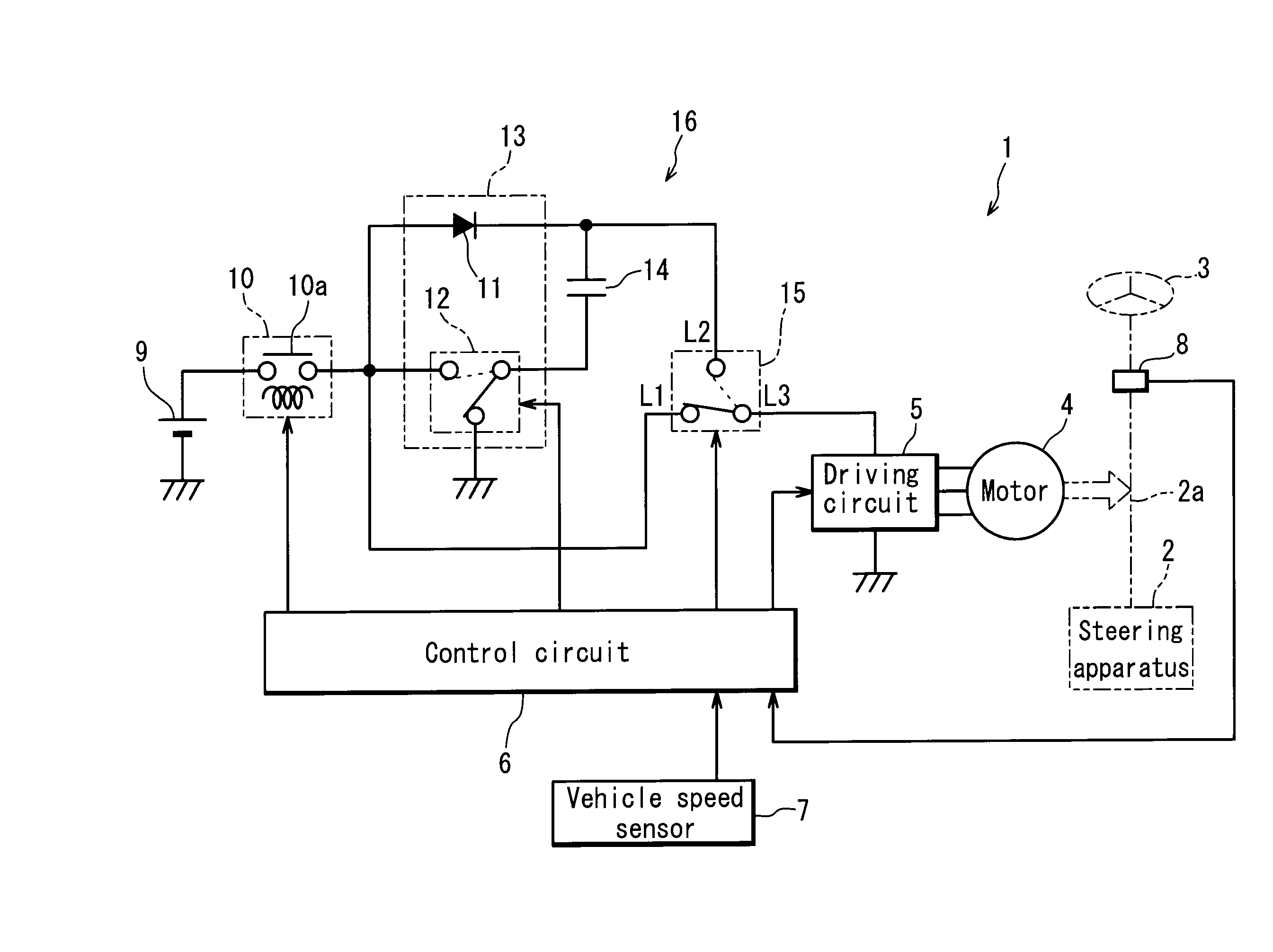
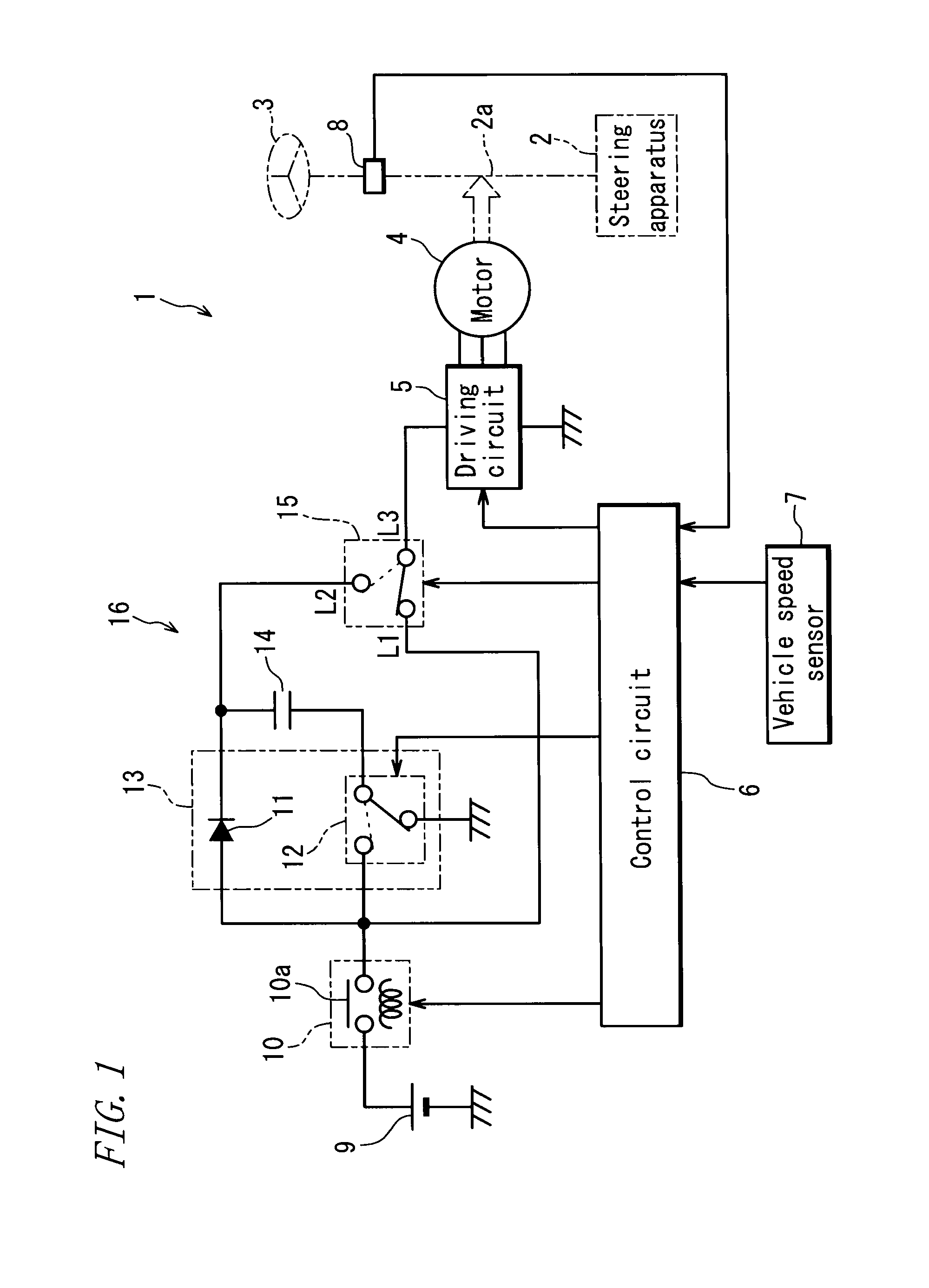
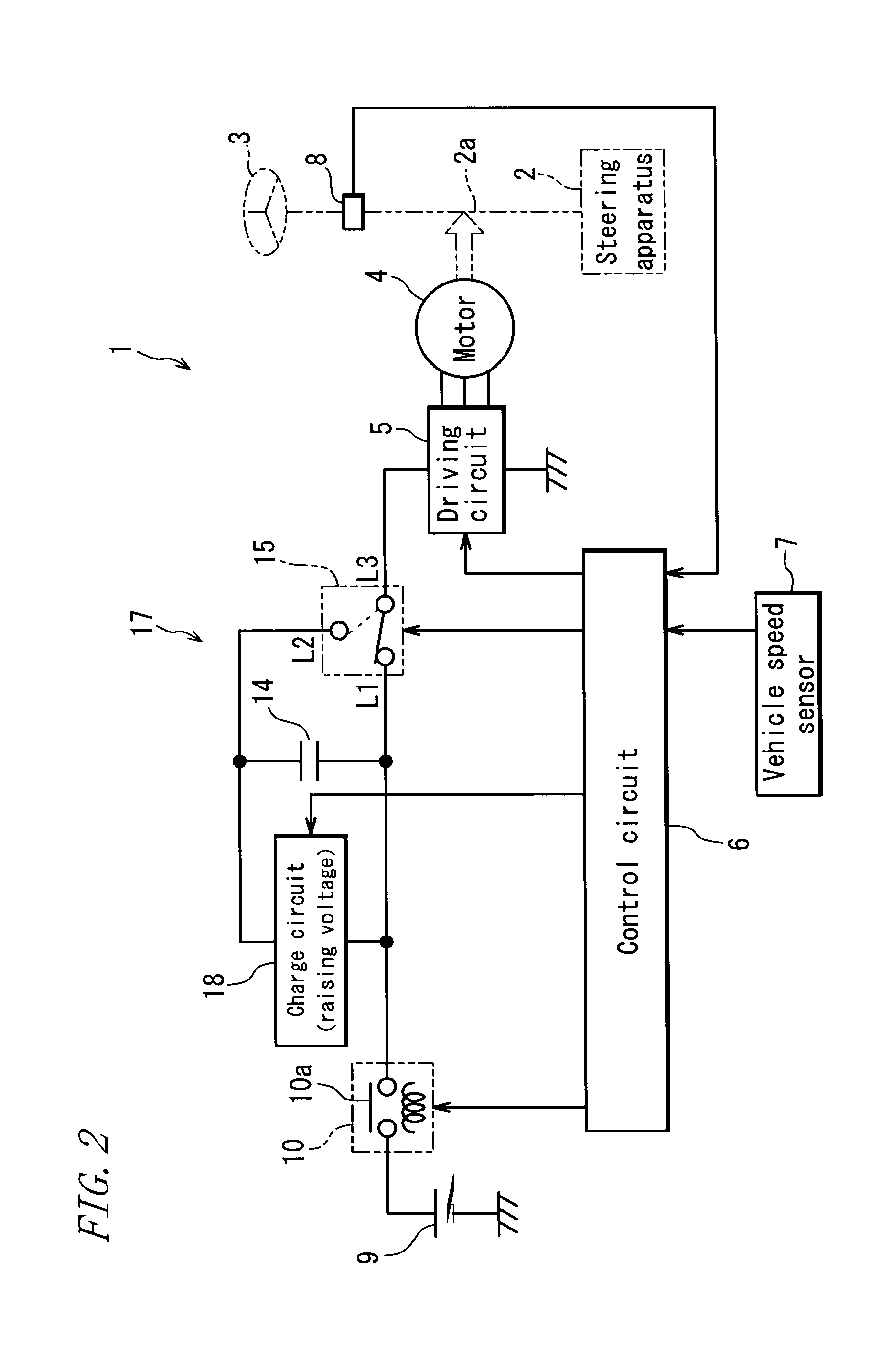
[0018]An electric power steering apparatus according to one embodiment of the present invention will be described hereinbelow with reference to the accompanying drawings. The circuit configuration of the electric power steering apparatus employing an auxiliary power supply is roughly classified into the following three types.

1>

[0019]A type that the auxiliary power supply is charged by a voltage of a battery and that the auxiliary power supply, when used, is connected in series with the battery as a main power supply

2>

[0020]A type that the battery is increased in voltage to charge the auxiliary power supply and that the auxiliary power supply, when used, is connected in series with the battery as the main power supply

3>

[0021]A type that the auxiliary power supply is charged by the voltage of the battery and that the auxiliary power supply, when used, is connected in parallel with the battery as the main power supply

[0022]FIG. 1 is a schematic diagram principally showing an electric c...


PUM


Abstract

In an electric power steering apparatus including a charge-discharge circuit 16 that selectively configures a first output mode in which only a main power supply including a battery 9 is used to supply an electric power to a motor 4 or a second output mode in which the main power supply and an auxiliary power supply 14 are used to supply the electric power to the motor 4, and a control circuit 6 that selects the output mode of the charge-discharge circuit 16 according to the electric power required for steering assist, the control circuit 6 selects the second output mode when the electric power required for steering assist in the first output mode becomes equal to or higher than an upward threshold value P1 or selects the first output mode when the electric power required for steering assist in the second output mode becomes equal to or lower than a downward threshold value P2 that is lower than the upward threshold value P1.

Description

TECHNICAL FIELD [0001]The present invention relates to an electric power steering apparatus that generates a steering assist force by a motor. More particularly, the invention relates to a configuration of electric circuit of the electric power steering apparatus.BACKGROUND ART[0002]The electric power steering apparatus is a machine which operates the motor for generating the steering assist force according to a steering torque applied by a driver. The recent years have seen a fast-growing demand for electric power steering apparatuses for use in large cars. Such a large car requires an increased steering assist force so that a larger amount of electric power must be supplied to the motor. In some cases, however, a battery alone may be unable to fully meet such a large power demand. In this connection, an arrangement has been proposed wherein an auxiliary power supply is provided in addition to the battery such that the normal power demand is met by the battery alone but when a larg...

Claims


Application Information

Patent Timeline
Patent Type & Authority Applications(United States)
IPC IPC(8): G06F19/00B62D5/04B62D6/00H02P6/06H02P6/08
CPCB62D5/0457H02P29/028H02J7/345B62D5/0481H02P29/032
Inventor NAGASE, SHIGEKI
Owner JTEKT CORP
Learn More