Bump-Resistant Pin Tumbler Lock

Inactive Publication Date: 2010-08-26
STUART CRAIG ROBERT
View PDF15 Cites 8 Cited by
  • Summary
  • Abstract
  • Description
  • Claims
  • Application Information

AI Technical Summary

Benefits of technology

[0011]Alternatively, it is an object of the invention to provide a bump-resistant pin-tumbler lock, or a plug for use in a bump-resistant pin-

Problems solved by technology

However, pick guns are not readily available to unauthorised individuals, require greater user skill and do not work well on paracentric keyways.
In addition, when compared to traditional methods of lock picking, ‘bump’ keys leave little or no evidence that the lock has been opened using a method other than inserting the correct key.
For example, if a bump key has been used to break into a house, there is often no sign of forced entry and an insurance company may be wary of paying insurance for any subsequent claim.
The availability of information, particularly on the Internet, on ‘

Method used


Image

  • Bump-Resistant Pin Tumbler Lock
  • Bump-Resistant Pin Tumbler Lock
  • Bump-Resistant Pin Tumbler Lock

Examples


Example

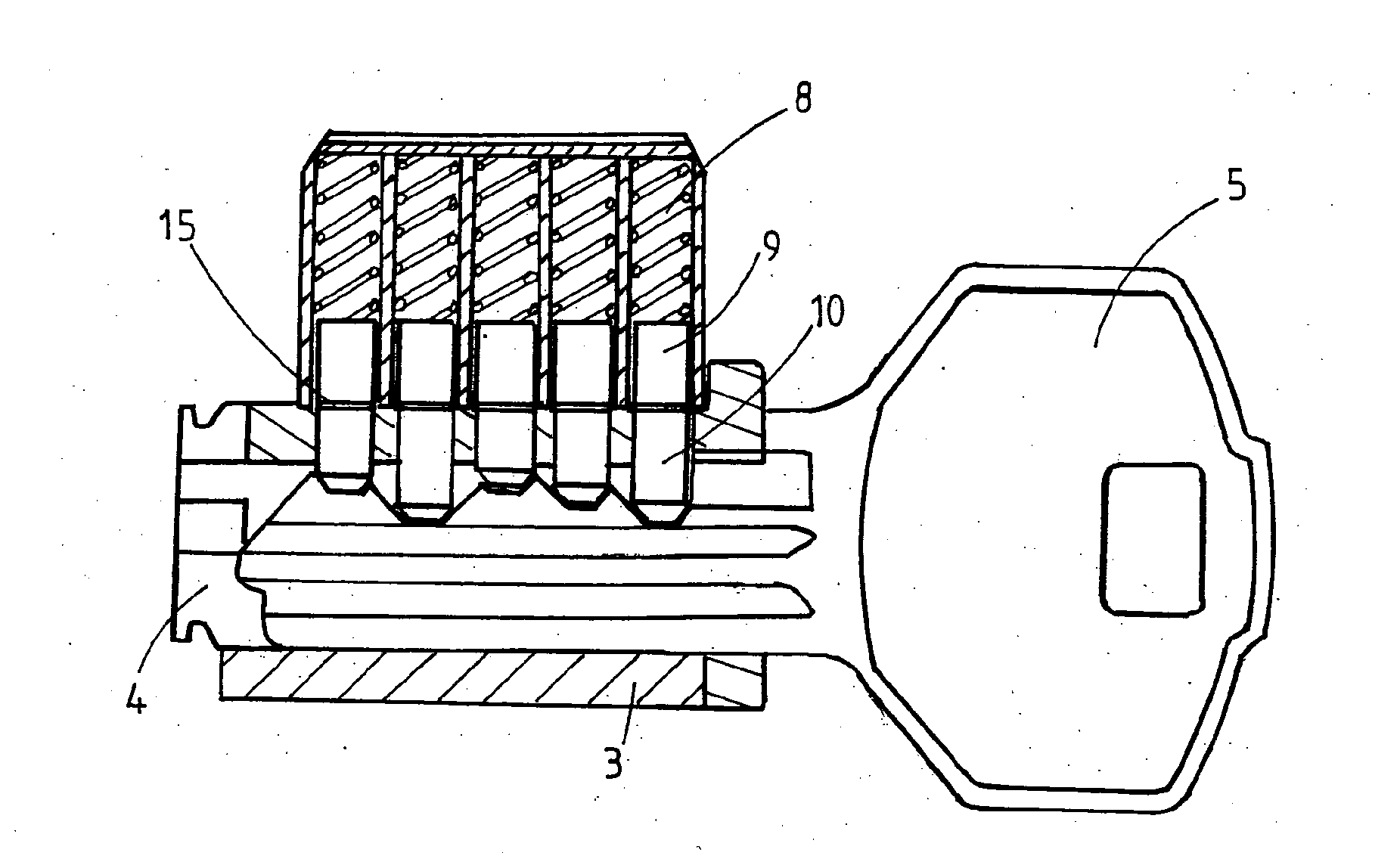
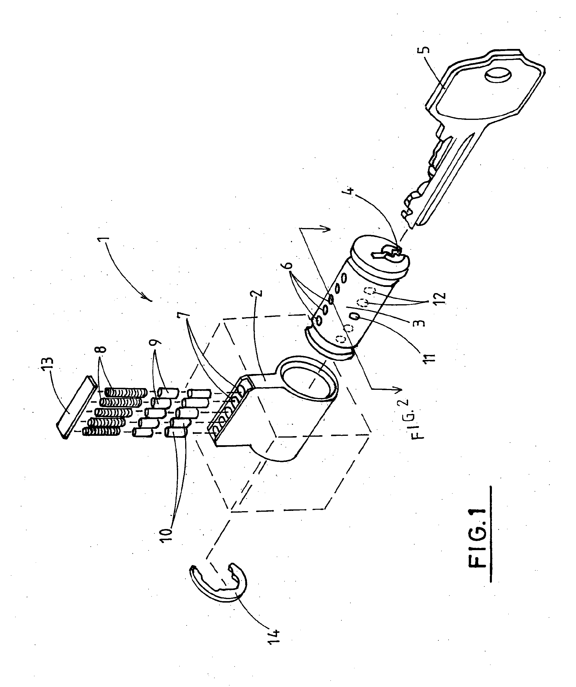
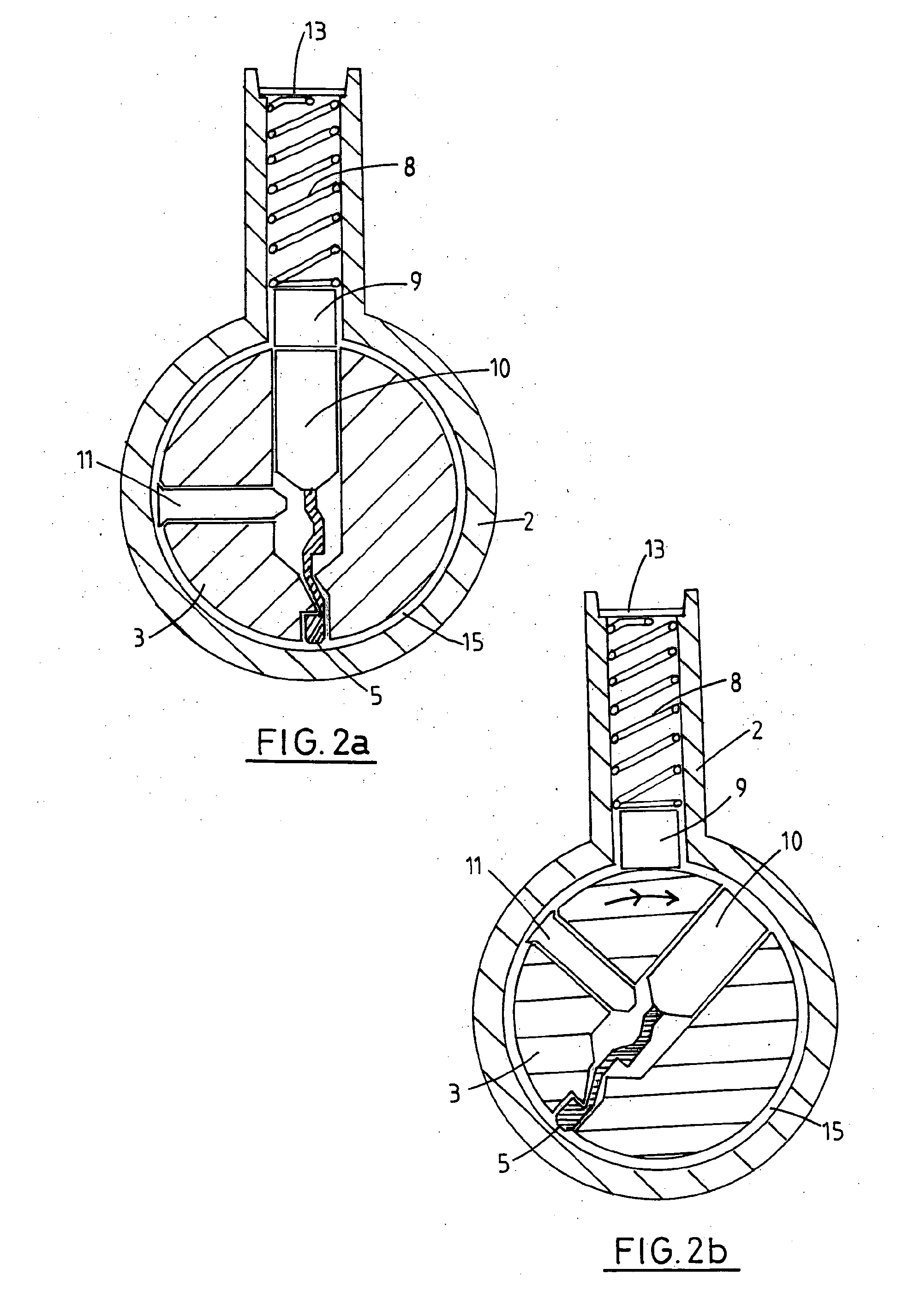
[0056]In broad terms, the invention provides and makes use of one or more obstructions (which are preferably removable and / or capable of being positioned in different configurations) which limit the travel of one or more corresponding bottom pins of a pin-tumbler lock in its chamber so that the one or more bottom pins will not sit on a bump key. This improves resistance to bumping because locks according to the invention have different possible combinations of resting positions of the bottom pins, thus bump keys appropriate therefor must be correspondingly configured. This makes bump keys largely impractical or at least raises the skill level required in the use thereof.

[0057]With reference to FIG. 1 the present invention provides a bump resistant pin-tumbler lock (1) including a housing (2). The housing houses a substantially cylindrical plug (3). The plug (3) extends substantially along the length of the housing and the plug is rotatable within the housing. The plug has a keyway (...


PUM

PropertyMeasurementUnit
Electrical resistanceaaaaaaaaaa
Heightaaaaaaaaaa

Abstract

A bump resistant pin-tumbler lock having a housing; a plug rotatably mounted within the housing and having a keyway; and a shear line defined between the interface between the plug and housing. The plug has one or more pin chambers extending from and orthogonally to the shear line and the keyway, wherein each pin chamber is capable of housing a bottom pin and is aligned with a corresponding driver chamber when the plug is in a locked position. Each driver chamber extends into the housing from and orthogonally to the shear line, includes a biasing means and is capable of housing one or more top pins. The plug further includes a bottom pin retaining means extending into one of the pin chambers so as to selectively retain a predetermined bottom pin in its respective pin chamber and prevent the predetermined bottom pin from fully extending into the pin chambers, such that, in use, kinetic energy cannot be transferred to the predetermined bottom pin from a bump member.

Description

[0001]The present invention relates generally to bump-resistant pin-tumbler locks. More particularly, this invention is directed to enhancing the security afforded by pin-tumbler locks.BACKGROUND[0002]The majority of locks currently in use around the world are ‘pin-tumbler’ locks and their design has changed little since their invention by Linus Yale in 1861. These locks are generally comprised of a lock plug which is rotatable inside a cylinder on insertion and rotation of the correct key in a keyway provided in the plug. The cylinder generally includes an in-line set of 5 or 6 pin chambers, each chamber containing a spring-loaded top pin adjacent to a bottom pin of varying length. The lock plug cannot be rotated within the lock housing without a key because the pins traverse the seam or shear line between the plug and housing, since each spring urges a corresponding pin to a position of maximum extension within the plug such that at least one pin is partly inside one of the pin ch...

Claims


Application Information

Patent Timeline
IPC IPC(8): E05B27/08B23P11/00
CPCE05B27/0007E05B27/0017Y10T29/49826E05B27/0057E05B27/005Y10T70/7605
Inventor STUART, CRAIG ROBERT
Owner STUART CRAIG ROBERT
Why Eureka
Try Eureka