Power line plug

a power line and plug technology, applied in the direction of coupling device connection, coupling device two-part connection, coupling/disengagement of coupling parts, etc., can solve the problems of plug non-competitive in the market and relatively increased manufacturing cost, and achieve the effects of reducing manufacturing cost, simple structure, and saving manpower

Inactive Publication Date: 2015-12-10
POWERSYNC INT
View PDF3 Cites 4 Cited by
  • Summary
  • Abstract
  • Description
  • Claims
  • Application Information

AI Technical Summary

Benefits of technology

[0015]By means of the foregoing structure, a thumb of a user may push up the pull lug from bottom to top, the pull lug is obliquely arranged at the fixing base, which facilitates a finger to hook the pull lug, and a force is applied to pull out the power line plug upward, and the plug pin of the power line plug is separated from the plug hole of the socket, and therefore advantages of rapidness and labor saving are provided. Therefore, the present invention sufficiently solves the problem of the first flat plug in the prior art shown in FIG. 1 and FIG. 2 that, when a draw

Problems solved by technology

However, the foregoing second flat plug in the prior art has a very complex structure and many components, the manufacturing cost is relatively increased

Method used


Image

  • Power line plug
  • Power line plug
  • Power line plug

Examples


Embodiment Construction

[0028]Detailed content and technical description relevant to the present invention are further described with embodiments, but it should be understood that, the embodiments are only used as exemplary description, but should not be construed as a limitation to implementation of the present invention.

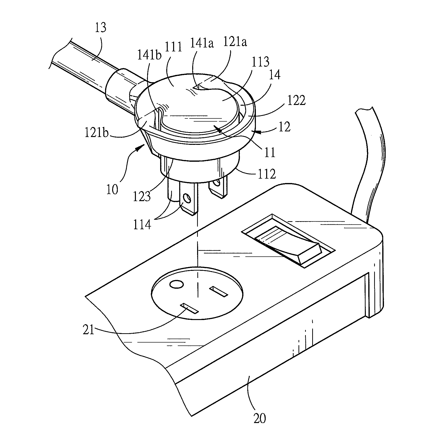
[0029]Referring to FIG. 5 to FIG. 8, FIG. 5 is a three-dimensional schematic view of a socket in cooperation according to an embodiment of the present invention; FIG. 6 is a three-dimensional view in another direction according to an embodiment of the present invention; FIG. 7 is a top view according to an embodiment the present invention; FIG. 8 is a front view according to an embodiment the present invention. The present invention discloses a power line plug, which is plugged into a socket 20 to connect to a power supply, and the power line plug 10 is circular, and includes: a fixing base 11, a pull lug 12 and a power line 13. The fixing base 11 is approximately semi-circular and has a ...


PUM


Abstract

A power line includes: a fixing base, a pull lug and a power line, where the fixing base has a connection portion, an abutting surface abutting the socket and an outer side with the back facing the abutting surface, the abutting surface is provided with a plurality of plug pins, and one of the plug pins is inserted into a plug hole of the socket; and the pull lug surrounds the periphery of the fixing base, an interval exists between the pull lug and the fixing base, the pull lug has a first end and a second end which are connected to the connection portion, and the first end and the second end have elastic deflection, so that the pull lug performs direction rotation by means of the first end and the second end, and one end of the power line is connected to the power line plug.

Description

BACKGROUND OF THE INVENTION[0001]1. Field of Invention[0002]The present invention relates to a power line plug, and particularly to a plug structure having a pull ring which provides convenience for a finger to hook, pull or separate from a socket.[0003]2. Related Art[0004]Accordingly, FIG. 1 and FIG. 2 show a first flat plug in the prior art, which includes a plug 1 and a semi-circular pull ring 2. The plug 1 is formed by fastening an upper cover 3 and a foundation 4, the upper cover 3 is provided with two vertically symmetrical upper grooves 5 adjacent to the periphery the upper cover 3, and the foundation 4 is also provided with two vertically symmetrical lower grooves 6 adjacent to the periphery of the foundation 4. After the upper cover 1 and the foundation 4 are fastened to form the plug 1, the upper groove 5 and the lower groove 6 are jointed so that two inner holes 7 are formed at left and right sides of the plug 1. Left and right sides of the pull ring 2 are each provided w...

Claims


Application Information

Patent Timeline
IPC IPC(8): H01R13/633H01R24/28
CPCH01R13/6335H01R2103/00H01R24/28
Inventor LIU, MENG-CHANG
Owner POWERSYNC INT
Why Eureka
Try Eureka