Method and apparatus for wire guide wear plate

a wear plate and wire guide technology, applied in the field of baling presses, can solve the problems of the door of the discharge chamber wearing against the sidewall of the wire guide member, and achieve the effects of convenient looping, low cost structure, and simple structur

Inactive Publication Date: 2006-09-26
L & P PROPERTY MANAGEMENT CO +1
View PDF12 Cites 3 Cited by
  • Summary
  • Abstract
  • Description
  • Claims
  • Application Information

AI Technical Summary

Benefits of technology

[0014]The present invention provides an improved design of a bale wire tying device which very reliably facilitates engaging the looped ends of the wire tie into a proper knot. Further, the bale wire tying device of the present invention is modular in construction, thereby permitting the tying device components to be replaced independently of the wire guide itself. Further, the tying device of the present invention has the further advantages of providing a simple, durable, low cost structure that is easier to use, more economical to service and overall provides a more user friendly operation.
[0015]In accordance with the principles of the present invention and in accordance with the described embodiments, the present invention provides a removable wear insert for attachment to a wire guide member. Previously, the door of the discharge chamber would wear against the sidewall of the wire guide member. The present invention resolves this problem by providing a wear insert that can be quickly and easily replaced. The wear insert cooperates with the door to form a portion of the discharge chamber. The wear insert includes a cutout that receives a portion of the door. In this manner, the dimensions of the discharge chamber can be accurately maintained in a cost effective manner by replacing the removable wear insert as required.

Problems solved by technology

Previously, the door of the discharge chamber would wear against the sidewall of the wire guide member.

Method used


Image

  • Method and apparatus for wire guide wear plate
  • Method and apparatus for wire guide wear plate
  • Method and apparatus for wire guide wear plate

Examples


Embodiment Construction

[0032]The following description of the preferred embodiment(s) is merely exemplary in nature and is in no way intended to limit the invention, its application, or uses.

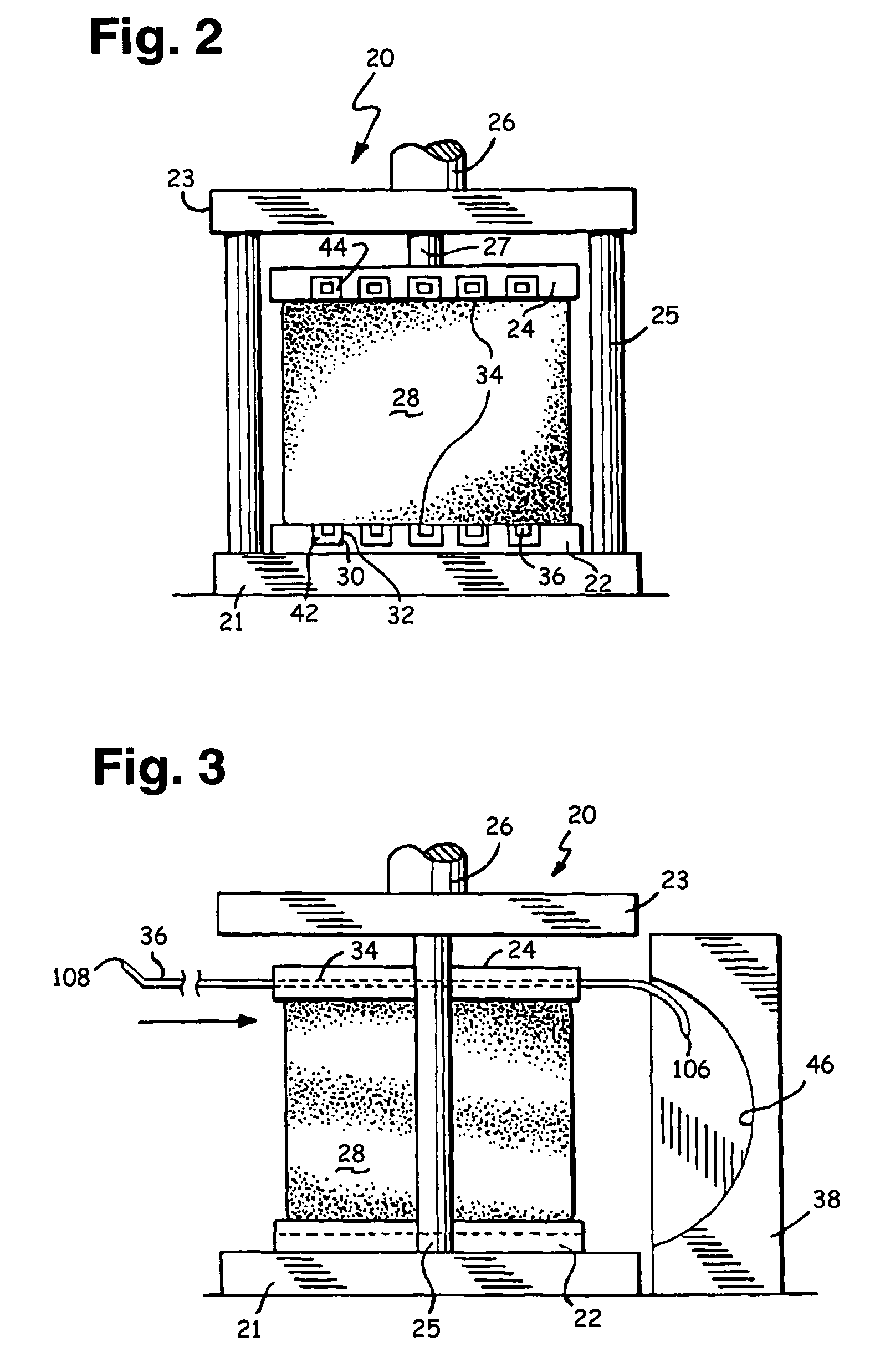
[0033]Referring to FIG. 2, a baling press 20 is schematically illustrated as having a stationary lower frame member 21 supporting a stationary lower platen 22 and a stationary upper frame member 23. The lower and upper frame members 21, 23 are connected by two tie bars 25 to form a rigid frame structure. The upper frame member 24 supports a hydraulic cylinder 26 having a piston 27 connected to a movable upper platen 24. The hydraulic piston and cylinder unit 26 functions to move the upper platen 24 in a generally vertical direction with respect to the lower platen 22, and thus, the baling press 20 is suitable for compressing material, for example, cotton, into a bale 28.

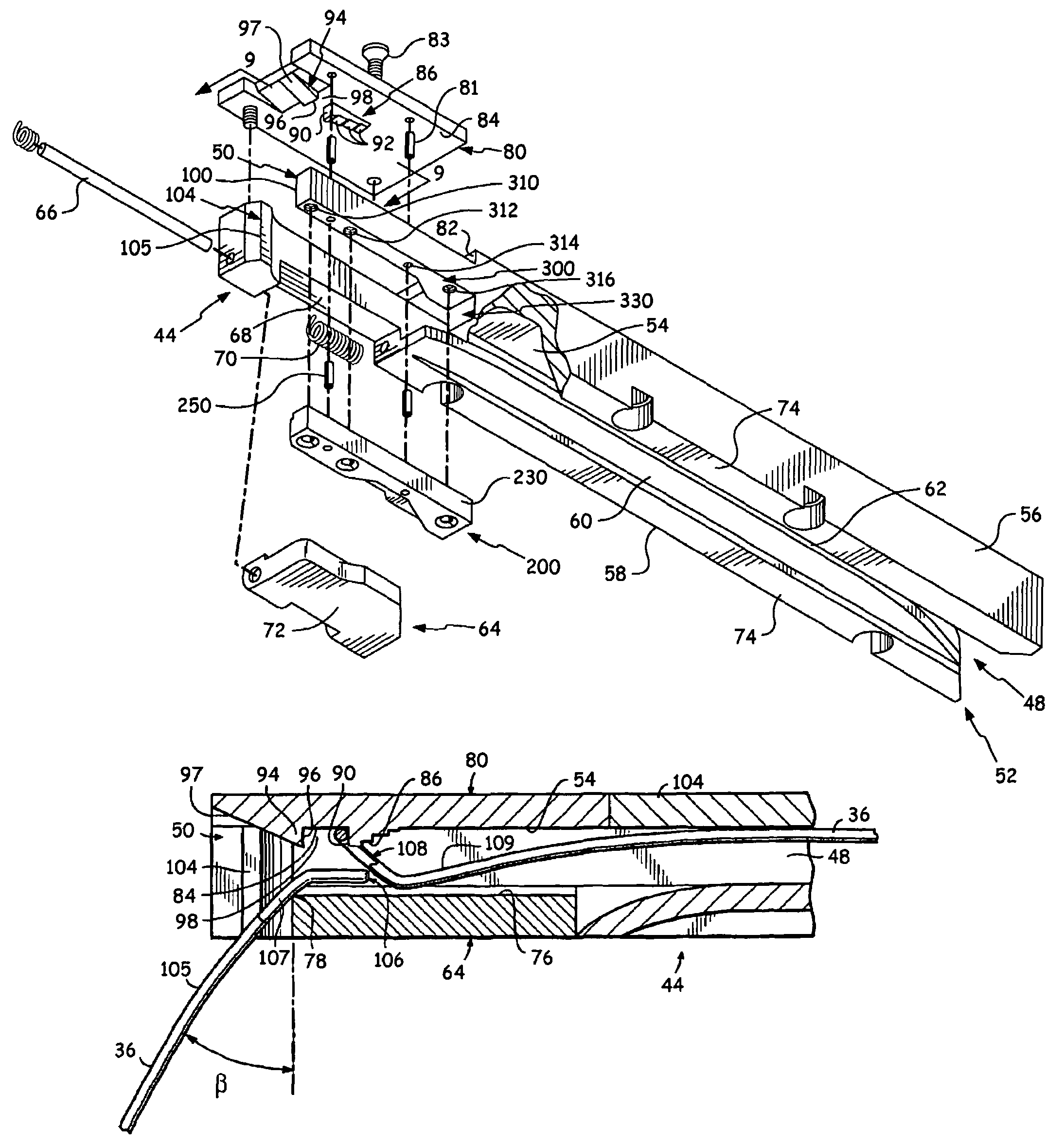
[0034]A plurality of opposing pairs of wire guide members 30 are mounted in slots 32 that extend between the front and rear of the press 20 in the low...


PUM


Abstract

A tying device and method of assembling same is disclosed. The tying device has a wire guide member adapted for mounting on an upper platen of a baling press. The wire guide member includes a top wall and side walls depending laterally from the top wall to form a channel. A door is pivotally mounted to one of the side walls, and the door having an inner, forward edge extending generally perpendicular to the side walls for guiding the wire tie into the channel. A removable wear insert is mounted to one of the side walls and has a cutout adapted to receive a portion of the door.

Description

CROSS-REFERENCE TO RELATED APPLICATIONS[0001]None.BACKGROUND OF THE INVENTION[0002]1. Field of the Invention[0003]This invention relates generally to the field of baling presses and more particularly, to an improved wire tie guide and tying device for a baling press and a method of assembling the wire tie guide.[0004]2. Related Art[0005]Wire baling of bulk materials has benefited from increased speed and reduced material cost through automation. Bulk materials include fibrous bulk materials, such as cotton and nylon. Fibrous materials are commonly formed into bales by simultaneous compression and binding. There is a continuing need in the automated baling art to improve the efficiency, reliability and accuracy of the bale binding process.[0006]Baling wire performance requirements vary depending upon the bulk material being baled. Such requirements range from industry standard specifications to general operational parameters, such as minimum speeds required for profitability. The Cot...

Claims


Application Information

Patent Timeline
Patent Type & Authority Patents(United States)
IPC IPC(8): B65B13/06B65B13/20
CPCB65B27/12B65B13/26
Inventor DANIEL, BARTON W.
Owner L & P PROPERTY MANAGEMENT CO
Why Eureka
Try Eureka