Evaporator surface structure of a circulating fluidized bed boiler and a circulating fluidized bed boiler with such an evaporator surface structure

Active Publication Date: 2015-05-26
AMEC FOSTER WHEELER ENERGIA
View PDF24 Cites 3 Cited by
  • Summary
  • Abstract
  • Description
  • Claims
  • Application Information

AI Technical Summary

Benefits of technology

[0005]The purpose of the present invention is to provide an evaporator surface structure for a circulating fluidized bed bo

Problems solved by technology

Since it is not advantageous to form the shape of the horizontal cross section of the boiler to be very oblong, nor to increase the height of the boiler too much, the total area of the evaporator surfaces formed by the outer walls of the furnace tends to remain too small in large boilers.
For example, if oxygen-enriched air is used instead of air as fluidizing gas, the surface area of the furnace walls available for evaporator surfaces may decrease even more.
Despite the openi

Method used


Image

  • Evaporator surface structure of a circulating fluidized bed boiler and a circulating fluidized bed boiler with such an evaporator surface structure
  • Evaporator surface structure of a circulating fluidized bed boiler and a circulating fluidized bed boiler with such an evaporator surface structure
  • Evaporator surface structure of a circulating fluidized bed boiler and a circulating fluidized bed boiler with such an evaporator surface structure

Examples


Embodiment Construction

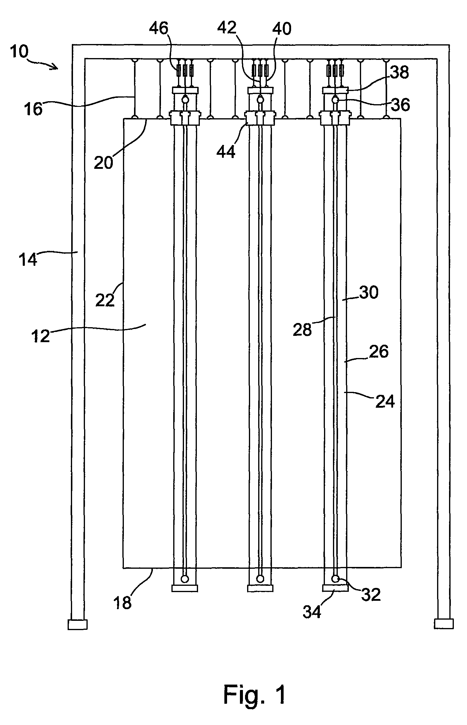
[0032]FIG. 1 illustrates a CFB boiler 10, in accordance with a preferred embodiment of the present invention, comprising a furnace 12 suspended to hang from a stationary supporting structure 14 by means of suspending means 16, for example, by hanger rods. The boiler in accordance with the invention may be a natural circulation boiler, in other words, a drum boiler, but, most preferably, it is a supercritical once-through utility boiler. The furnace is limited by a bottom 18, a ceiling 20 and sidewalls 22, which are usually of a water tube structure. The furnace is also provided with other conventional parts of a CFB boiler, such as inlet means for fuel and combustion air, outlet means for flue gas and bottom ash, as well as dust separators and return ducts connected thereto. For simplicity, these details, which are irrelevant in view of the present invention, are not shown in FIG. 1.

[0033]The outer walls 22 of the furnace are normally manufactured of water tube panels, in which the ...


PUM


Abstract

An evaporator surface structure of a circulating fluidized bed boiler having a furnace that is enclosed by sidewalls and has a bottom and a ceiling. The evaporator surface structure includes at least one vertical and separate evaporator surface unit that is spaced apart from the sidewalls of the furnace. The at least one evaporator surface unit (i) is formed of planar water tube panels that extend from the bottom of the furnace to the ceiling of the furnace, and (ii) consists of two cross-wise joined vertical water tube panels.

Description

[0001]This application is a U.S. national stage application of PCT International Application No. PCT / FI2007 / 050284, filed May 18, 2007, and published as PCT Publication No. WO 2007 / 135239 A2, and which claims priority from Finnish patent application number 20060488, filed May 18, 2006.FIELD OF THE INVENTION[0002]The present invention relates to an evaporator surface structure of a circulating fluidized bed boiler (CFB boiler) and a circulating fluidized bed boiler with such an evaporator surface structure. The invention especially relates to an evaporator surface structure arranged in a furnace of a large CFB boiler, typically, a once-through utility boiler of over 400 MWe.BACKGROUND OF THE INVENTION[0003]In CFB boilers, the evaporation of heated feed water, i.e., boiling takes place mostly by means of water tube panels in the outer walls of the boiler furnace. When increasing the efficiency of the boiler, the cross-sectional area of the furnace must be increased proportionally with...

Claims


Application Information

Patent Timeline
IPC IPC(8): F22B21/20F22B29/06
CPCF22B29/062F22B31/0038F22B37/143F22B37/148F22B37/244F23C10/18F22B31/00F23C10/00F22B29/06F22B37/14
Inventor LANKINEN, PENTTI
Owner AMEC FOSTER WHEELER ENERGIA
Why Eureka
Try Eureka