Substrate Processing Apparatus, Substrate Processing Method, and Drain Cup Cleaning Method

a substrate and processing method technology, applied in the direction of cleaning process and apparatus, chemistry apparatus and processes, cleaning using liquids, etc., can solve the problems of difficult to solve problems, insufficient supply of rinsing liquid, adverse effects on substrate drying performance, etc., to reduce the rotational speed of substrate, increase the flow rate of rinsing liquid, and reduce the effect of substrate rotation speed

Active Publication Date: 2010-08-26
TOKYO ELECTRON LTD
View PDF4 Cites 15 Cited by
  • Summary
  • Abstract
  • Description
  • Claims
  • Application Information

AI Technical Summary

Benefits of technology

[0021]According to a fourth aspect of the present invention, there is provided a computer readable storage medium that stores a control program for execution on a computer, which is used for controlling a substrate processing apparatus that comprises a substrate holding member configured to rotate along with a substrate held thereon in a horizontal state, a rotation mechanism configured to rotate the substrate holding member, a process liquid supply mechanism configured to supply a process liquid onto the substrate, a rinsing liquid supply mechanism configured to supply a rinsing liquid onto the substrate, and an annular drain cup disposed around the rotary cup and configured to receive and discharge the process liquid or rinsing liquid scattered from the substrate being rotated, the drain cup including an outer sidewall that surrounds a lateral side of an edge of the substrate and an internal wall that surrounds a lower side of the edge of the substrate, wherein the control program, when executed, causes the computer to control the substrate processing apparatus to conduct a substrate processing method comprising: performing a substrate process on the substrate while rotating the substrate held on the substrate holding member by the rotation mechanism and supplying the process liquid onto the substrate from the process liquid supply mechanism; and then performing a rinsing process while rotating the substrate in a similar way and supplying the rinsing liquid onto the substrate from the rinsing liquid supply mechanism, wherein the rinsing process comprising adjusting a rotational speed of the substrate to be the same as the rotational speed used in the substrate process while supplying the rinsing liquid, raising a liquid level of the rinsing liquid inside the drain cup by decreasing the rotational speed of the substrate or increasing a flow rate of the rinsing liquid, and raising a reach position of the rinsing liquid on the outer sidewall of the drain cup by increasing the rotational speed of the substrate.
[0022]According to a fifth aspect of the present invention, there is provided a computer readable storage medium that stores a control program for execution on a computer, which is used for controlling a substrate processing apparatus that comprises a substrate holding member configured to rotate along with a substrate held thereon in a horizontal state, a rotation mechanism configured to rotate the substrate holding member, a process liquid supply mechanism configured to supply a process liquid onto the substrate, a rinsing liquid supply mechanism configured to supply a rinsing liquid onto the substrate, and an annular drain cup disposed around the rotary cup and configured to receive and discharge the process liquid or rinsing liquid scattered from the substrate being rotated, the drain cup including an outer sidewall that surrounds a lateral side of an edge of the substrate and an internal wall that surrounds a lower side of the edge of the substrate, wherein the control program, when executed, causes the computer to control the substrate processing apparatus to conduct a drain cup cleaning method for cleaning the drain cup, the method comprising: holding the substrate or a dummy substrate on the substrate holding member; rotating the substrate or dummy substrate while supplying the rinsing liquid onto the substrate or dummy substrate, thereby rinsing a process liquid flow passage of the drain cup by the rinsing liquid thrown off from the substrate or dummy substrate; raising a liquid level of the rinsing liquid inside the drain cup by decreasing the rotational speed of the substrate or dummy substrate or increasing a flow rate of the rinsing liquid, as compared to that used in said rinsing a process liquid flow passage, and raising a reach position of the rinsing liquid on the outer sidewall of the drain cup by increasing the rotational speed of the substrate or dummy substrate, as compared to that used in said rinsing a process liquid flow passage.
[0023]According to the present invention, while a substrate is held on the substrate holding member, a rinsing process or cup cleaning is preformed by first adjusting a rotational speed of the substrate to be the same as the rotational speed used in the substrate process while supplying the rinsing liquid, and then raising a liquid level of the rinsing liquid inside the drain cup by decreasing the rotational speed of the substrate or increasing a flow rate of the rinsing liquid, and raising a reach position of the rinsing liquid on the outer sidewall of the drain cup by increasing the rotational speed of the substrate. Consequently, the rinsing liquid can be sufficiently supplied overall inside the drain cup, so that the process liquid is almost entirely removed from inside the drain cup.

Problems solved by technology

Specifically, if the alkaline chemical liquid or acidic chemical liquid are left on the drain cup after the rinsing process, the substrate drying performance is adversely affected by formation of salts due to evaporation of the chemical liquid or reaction between alkaline and acidic chemical liquids continuously used for the cleaning process.
However, in conventional rinsing processes, the rinsing liquid cannot be sufficiently supplied overall inside the drain cup, and so the process liquid is left inside the drain cup, and makes it difficult to solve the problem described above.
There is a case where the drain cup is provided with a cleaning mechanism for performing a cup cleaning process, but this brings about problems such that the apparatus becomes complex and bulky.

Method used


Image

  • Substrate Processing Apparatus, Substrate Processing Method, and Drain Cup Cleaning Method
  • Substrate Processing Apparatus, Substrate Processing Method, and Drain Cup Cleaning Method
  • Substrate Processing Apparatus, Substrate Processing Method, and Drain Cup Cleaning Method

Examples


Embodiment Construction

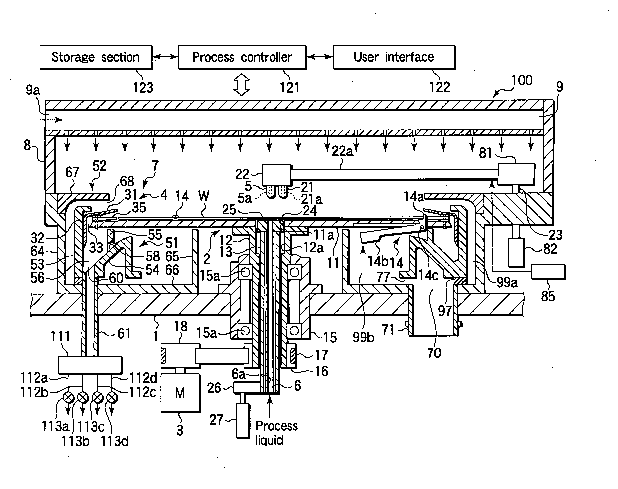
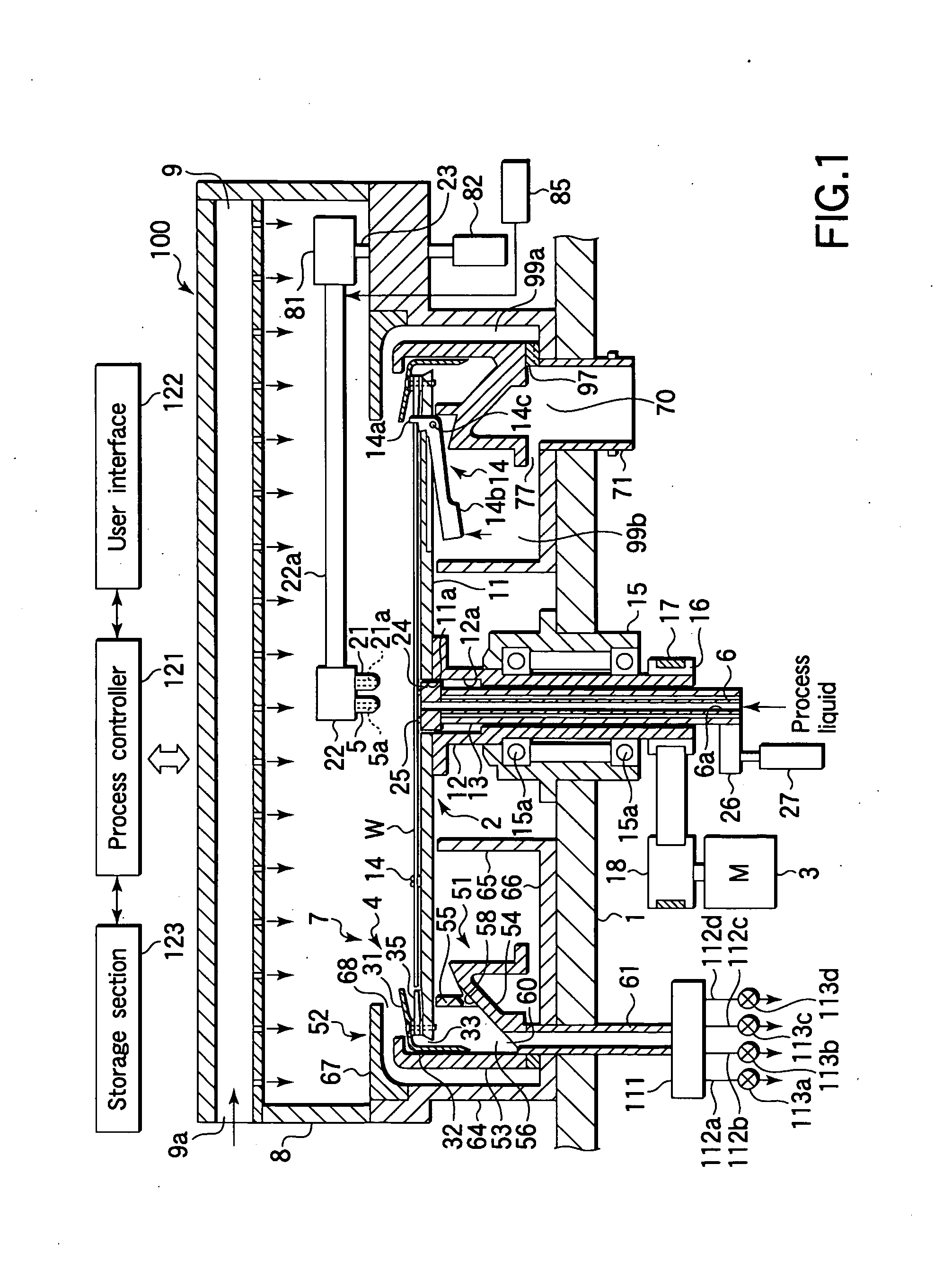
[0032]An embodiment of the present invention will now be described with reference to the accompanying drawings. Hereinafter, an explanation will be given of a case where the present invention is applied to a liquid processing apparatus that can perform a cleaning process on the front and back surfaces of a semiconductor wafer (which will be simply referred to as “wafer”, hereinafter).

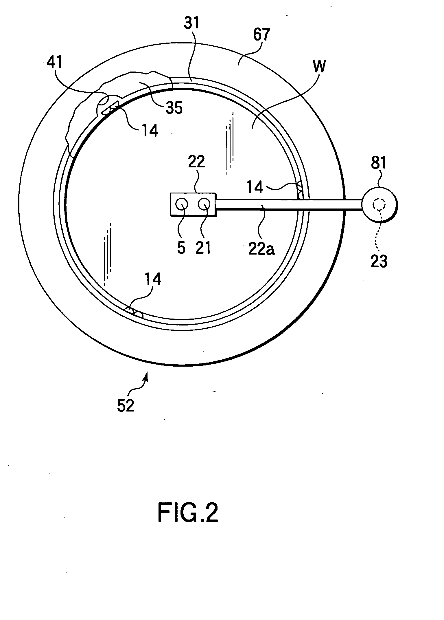
[0033]FIG. 1 is a sectional view schematically showing the structure of a substrate processing apparatus according to an embodiment of the present invention. FIG. 2 is a plan view of the substrate processing apparatus shown in FIG. 1. FIG. 3 is a view schematically showing a process liquid supply mechanism and a rinsing liquid supply mechanism used in the substrate processing apparatus shown in FIG. 1. FIG. 4 is an enlarged sectional view showing an exhaust / drain section used in the substrate processing apparatus shown in FIG. 1.

[0034]A plurality of substrate processing apparatuses 100 are disposed in a...


PUM

PropertyMeasurementUnit
flow rateaaaaaaaaaa
flow rateaaaaaaaaaa
timeaaaaaaaaaa

Abstract

A substrate processing apparatus includes a substrate holding member configured to rotate along with a wafer (W) held thereon and a drain cup (51) configured to surround the wafer (W). A cleaning process is performed by rotating the wafer (W) while supplying a process liquid onto the wafer (W), and then a rinsing process is performed by rotating the wafer (W) in a similar way while supplying a rinsing liquid onto the wafer (W). The rinsing process is performed by first adjusting a rotational speed of the wafer (W) to be the same as the rotational speed used in the cleaning process while supplying the rinsing liquid, and then raising a liquid level of the rinsing liquid inside the drain cup (51) by decreasing the rotational speed of the wafer (W) or increasing a flow rate of the rinsing liquid, and raising a reach position of the rinsing liquid on the outer sidewall of the drain cup (51) by increasing the rotational speed of the wafer (W).

Description

TECHNICAL FIELD[0001]The present invention relates to a substrate processing apparatus and substrate processing method for performing a predetermined liquid process, such as a cleaning process, on a substrate, such as a semiconductor wafer. The present invention further relates to a drain cup cleaning method for cleaning a drain cup configured to receive drainage in the substrate processing apparatus.BACKGROUND ART[0002]In the process of manufacturing semiconductor devices or flat panel display devices (FPD), liquid processes are frequently used, in which a process liquid is supplied onto a target substrate, such as a semiconductor wafer or glass substrate. For example, processes of this kind encompass a cleaning process for removing particles and / or contaminants deposited on a substrate.[0003]As a substrate processing apparatus used for this purpose, there is known an apparatus in which a substrate, such as a semiconductor wafer, is held on a spin chuck, and a process liquid, such ...

Claims


Application Information

Patent Timeline
Patent Type & Authority Applications(United States)
IPC IPC(8): B08B7/04B08B3/00
CPCH01L21/68728H01L21/67051H01L21/304
Inventor NANBA, HIROMITSUITO, NORIHIRO
Owner TOKYO ELECTRON LTD
Why Eureka
Try Eureka