Cooling system for a vehicle

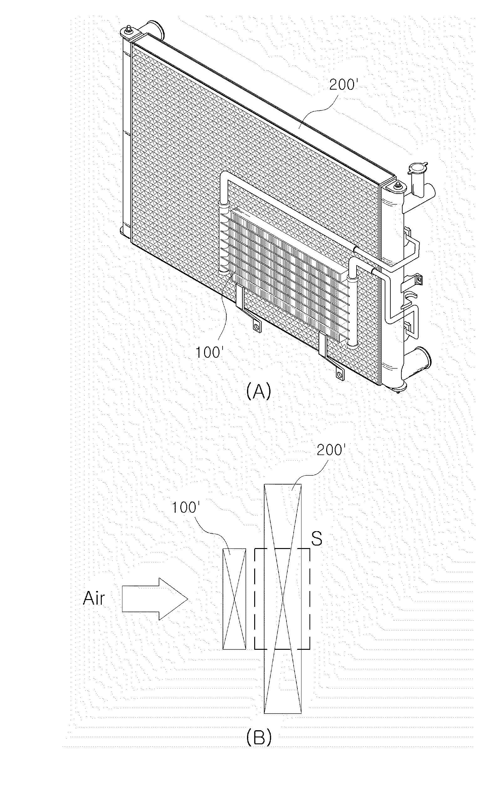
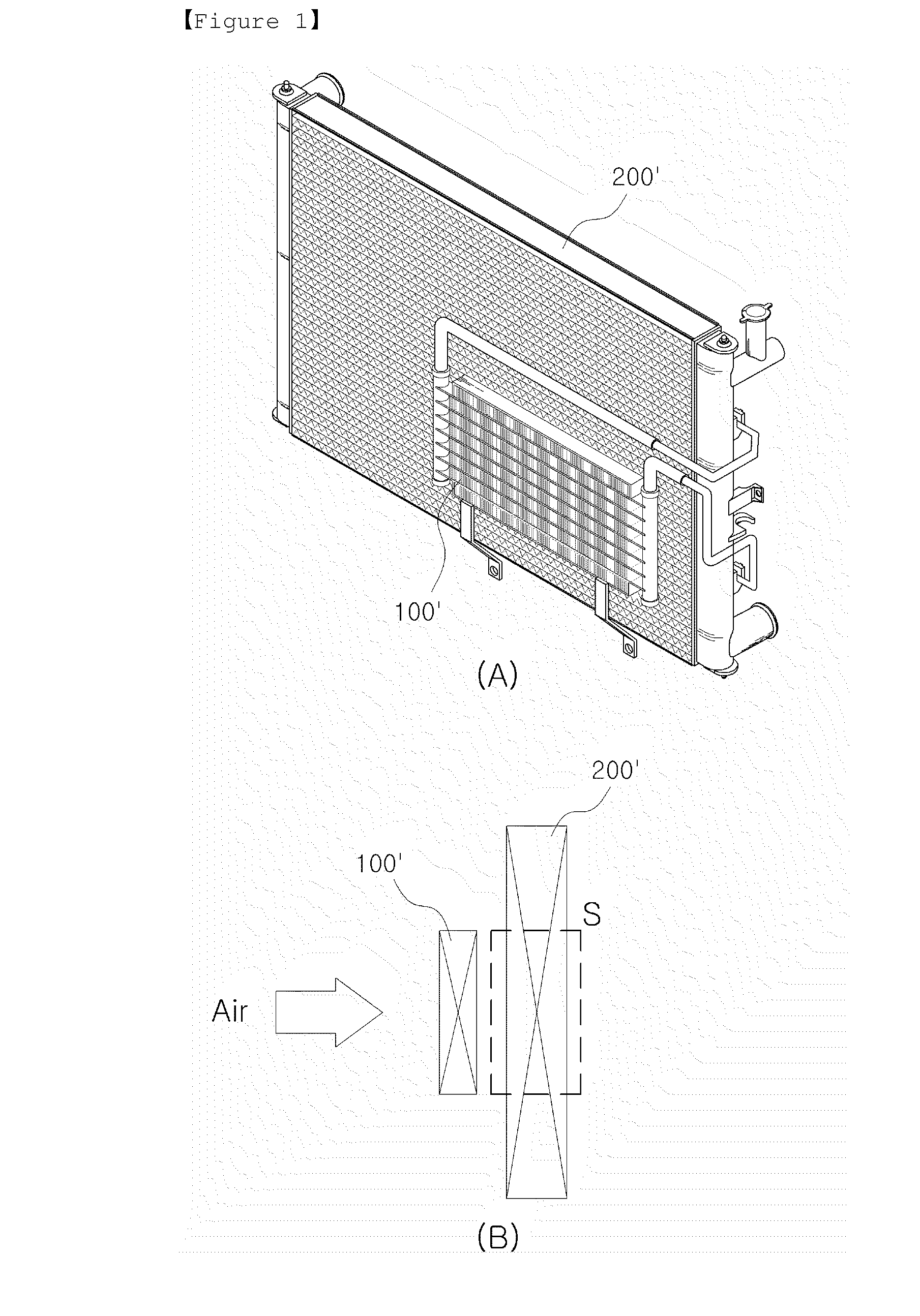
a technology for cooling systems and vehicles, applied in steam/vapor condensers, lighting and heating apparatus, stationary conduit assemblies, etc., can solve the problems of inability to perform the functions of the condenser, the heat exchange performance of the condenser b>200/b>′ is considerably deteriorated, and the engine parts and the like may be damaged, etc., to achieve the effect of reducing the viscosity of oil ratio ratio ratio ratio ratio ratio ratio ratio ratio ratio ratio ratio ratio ratio ratio ratio ratio ratio ratio ratio ratio ratio ratio ratio ratio ratio ratio ratio ratio ratio ratio ratio ratio ratio ratio ratio ratio ratio ratio ratio ratio ratio ratio ratio ratio ratio ratio ratio ratio ratio ratio ratio ratio ratio ratio ratio ratio ratio ratio ratio ratio ratio ratio ratio ratio ratio ratio ratio ratio ratio ratio ratio ratio ratio ratio ratio ratio ratio ratio ratio ratio ratio ratio ratio ratio ratio ratio ratio ratio ratio ratio ratio ratio ratio ratio ratio ratio ratio ratio ratio ratio ratio ratio ratio ratio ratio ratio ratio ratio ratio ratio ratio ratio ratio ratio ratio ratio ratio ratio ratio ratio ratio ratio ratio ratio ratio ratio ratio ratio ratio ratio ratio ratio ratio ratio ratio ratio ratio ratio ratio ratio ratio ratio ratio ratio ratio ratio ratio ratio ratio ratio ratio ratio ratio ratio ratio ratio ratio ratio ratio ratio ratio ratio ratio ratio ratio ratio ratio ratio ratio ratio ratio ratio ratio ratio ratio ratio ratio ratio ratio ratio ratio ratio ratio ratio ratio ratio ratio ratio ratio ratio ratio ratio ratio ratio ratio ratio ratio ratio ratio ratio ratio ratio ratio ratio ratio ratio ratio ratio ratio ratio ratio ratio ratio ratio ratio ratio ratio ratio ratio ratio ratio ratio ratio ratio ratio ratio ratio ratio ratio ratio ratio ratio ratio ratio ratio ratio ratio ratio ratio ratio ratio ratio ratio ratio ratio ratio ratio ratio ratio ratio ratio ratio ratio ratio ratio ratio ratio ratio ratio ratio ratio ratio ratio ratio ratio ratio ratio ratio ratio ratio ratio ratio ratio ratio ratio ratio ratio ratio ratio ratio ratio ratio ratio ratio ratio ratio ratio ratio ratio ratio ratio ratio ratio ratio ratio ratio ratio ratio ratio ratio ratio ratio ratio ratio ratio ratio ratio ratio ratio ratio ratio ratio ratio ratio ratio ratio ratio ratio ratio ratio ratio ratio ratio ratio ratio ratio ratio ratio ratio ratio ratio ratio ratio ratio ratio ratio ratio ratio ratio ratio ratio ratio ratio ratio ratio ratio ratio ratio ratio ratio ratio ratio ratio ratio ratio ratio ratio ratio ratio ratio ratio ratio ratio ratio ratio ratio ratio ratio ratio ratio ratio ratio ratio ratio ratio ratio ratio ratio ratio ratio ratio ratio ratio ratio ratio ratio ratio ratio ratio ratio ratio ratio ratio ratio ratio

Active Publication Date: 2010-08-26
HANON SYST
View PDF13 Cites 17 Cited by
  • Summary
  • Abstract
  • Description
  • Claims
  • Application Information

AI Technical Summary

Benefits of technology

[0016]According to the present invention, since the oil is cooled by the two oil cooler, i.e., the first oil cooler which is integrally formed with the condenser and the second oil cooler which is formed at the radiator, the heat exchange performance can be remarkably increased, comparing with the conventional oil cooler. Further, in the second oil cooler in which the oil is cooled by the cooling water of the radiator, since the cooling water has a higher temperature than the oil at the early stage of starting that an external temperature is low, the heat is transferred to the oil having a high viscosity due to the low external temperature, and thus the viscosity of the oil can be lowered. Therefore, it is possible to prevent the low-temperature impact without other parts like the bypass valve. Furthermore, since the oil can be cooled by using the simple structure which has not the bypass valve, it is possible to facilely control the cooling system. In addition, since the parts for the bypass valve are omitted, the cost of product can be reduced, and also due to the omission of the bypass valve, the space utility in the engine room can be maximized.

Problems solved by technology

If the oil is excessively heated, a viscosity of the oil is lowered, and thus it is not possible to perform its functions (i.e., removing of the friction and the maintaining of airtight condition).
Particularly, since the function of removing the friction is deteriorated, it is apprehended that parts of the engine and the like may be damaged.
However, in the conventional oil cooler 100′ and condenser 200′ as shown in FIG. 1B, when the air blows to a portion where the oil cooler 100′ and the condenser 200′ are overlapped with each other, since the air should pass through the two kinds of heat exchangers, air resistance is remarkably increased and thus heat exchange performance of the condenser 200′ is considerably deteriorated.
However, even in case of the condenser integrated with the oil cooler, there are some problems.
First, since the only way to improve the cooling performance of the oil cooler 100″ and the condenser 200″ is to change a height or a material of each tube, there is a limit to the improvement of the cooling performance.
Therefore, in case of the cold region or the winter season that the temperature is very low, since the oil is further cooled by the oil cooler 100″ in spite that its viscosity is higher than need be at the early stage of starting, it is apprehended that parts of the engine may be damaged.
However, when such the bypass valve 140″ is used, it further complicates control of the cooling system.
Moreover, since further parts like the bypass valve 140″, which are accessorily necessary, are required, a product price is increased, and an internal space in an engine room becomes narrow.

Method used


Image

  • Cooling system for a vehicle
  • Cooling system for a vehicle
  • Cooling system for a vehicle

Examples


Embodiment Construction

[0025]100′, 100″: first oil cooler[0026]111a: first oil cooler inlet port[0027]111b: first oil cooler outlet port[0028]112: first oil cooler tube[0029]113: first oil cooler fin[0030]120: second oil cooler[0031]121a: second oil cooler inlet port[0032]121b: second oil cooler outlet port[0033]120A: hollow pipe type oil cooler[0034]120B: double pipe type oil cooler[0035]120B1: external pipe[0036]120B2: internal pipe[0037]120B3: internal fin[0038]200: condenser[0039]210: tank[0040]220: condenser tube[0041]230: condenser fin[0042]240: baffle[0043]300: radiator[0044]310: radiator tank[0045]320: radiator tube[0046]330: radiator fin

BEST MODE

[0047]Hereinafter, the embodiments of the present invention will be described in detail with reference to accompanying drawings.

[0048]FIG. 3 is a perspective view of a cooling system for a vehicle according to the present invention. As shown in FIG. 3, a cooling system for a vehicle of the present invention includes a first oil cooler 110 which is integra...


PUM


Abstract

The cooling system for a vehicle comprises a heat exchanger in which a condenser 200 comprising a plurality of tubes 112, 220; a pair of tanks 210; and fins 113, 230 and in which a condenser 200 comprised of portions 210B, 220, 230 through which the refrigerant is flowed is integrally formed with a first oil cooler 110 comprised of portions 210A, 112, 113 through which the oil is flowed; a radiator 300 which comprises a plurality of radiator tubes 320; a pair of radiator tanks 310; and radiator fins 330, and which is positioned at a down stream of the condenser 200 in the air blow direction; and a second oil cooler 120 which is provided in one of the radiator tanks 310 of the radiator 300.

Description

TECHNICAL FIELD [0001]The present invention relates to a cooling system for a vehicle, and more particularly, to a cooling system for a vehicle, which has an improved structure for enhancing heat exchanging performance and preventing low temperature impact.BACKGROUND ART[0002]A heat exchanger serves between two environments, which have a difference in temperature, to absorb heat from one side and then emit the heat to the other side. In a general air conditioning system of a vehicle including evaporator for absorbing heat from the periphery thereof, a compressor for compressing refrigerant, a condenser for emitting the heat to the periphery thereof and an expansion valve for expanding the refrigerant, the evaporator, the condenser and the like are the typical heat exchangers. In the air conditioning system, the gaseous refrigerant introduced from the evaporator to the compressor is compressed at high temperature and high pressure, and while the compressed refrigerant is liquefied by...

Claims


Application Information

Patent Timeline
Patent Type & Authority Applications(United States)
IPC IPC(8): F28F9/02
CPCF28D1/0435F28D1/0443F28D1/0452F28F2009/0287F28D2021/0084F28D2021/0089F28F9/0234F28D1/0461F28F9/00
Inventor MIN, EUN GIJUN, GIL WOONGJANG, JUN-ILKIM, BYUNG-JOOJEONG, SUN ANLEE, SANG OK
Owner HANON SYST
Why Eureka
Try Eureka