Wall hanger

Active Publication Date: 2010-08-26
THE HILLMAN GRP INC
View PDF12 Cites 32 Cited by
  • Summary
  • Abstract
  • Description
  • Claims
  • Application Information

AI Technical Summary

Benefits of technology

[0010]In one embodiment of the present invention, the arm includes a spring arrangement between the shoulder and a portion of the arm carrying the sharp pointed end. The spring arrangement preferably has an arcuate shape between the shoulder and the portion of the arm carrying the sharp pointed end. The arcuate shape has curves so that a first portion of the arcuate shape extends from the shoulder to a p

Problems solved by technology

It has been found, however, that some installers find this hanger to be difficult to be mounted on a wall because it is difficult to handle the clip and plate, particularly to nailing the plate in place with the clip dangling fro

Method used


Image

  • Wall hanger
  • Wall hanger
  • Wall hanger

Examples


Example

DETAILED DESCRIPTION OF THE DRAWING

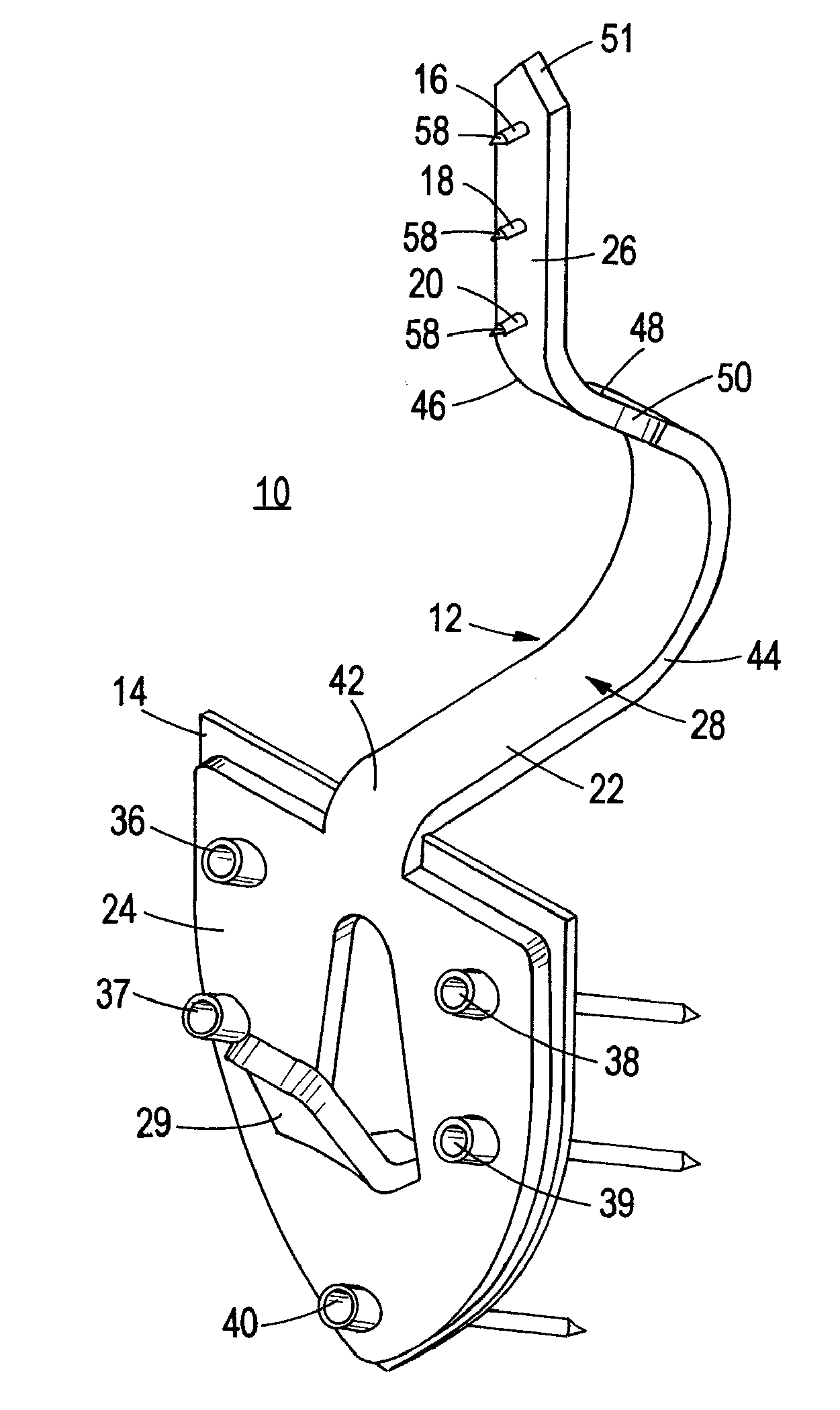
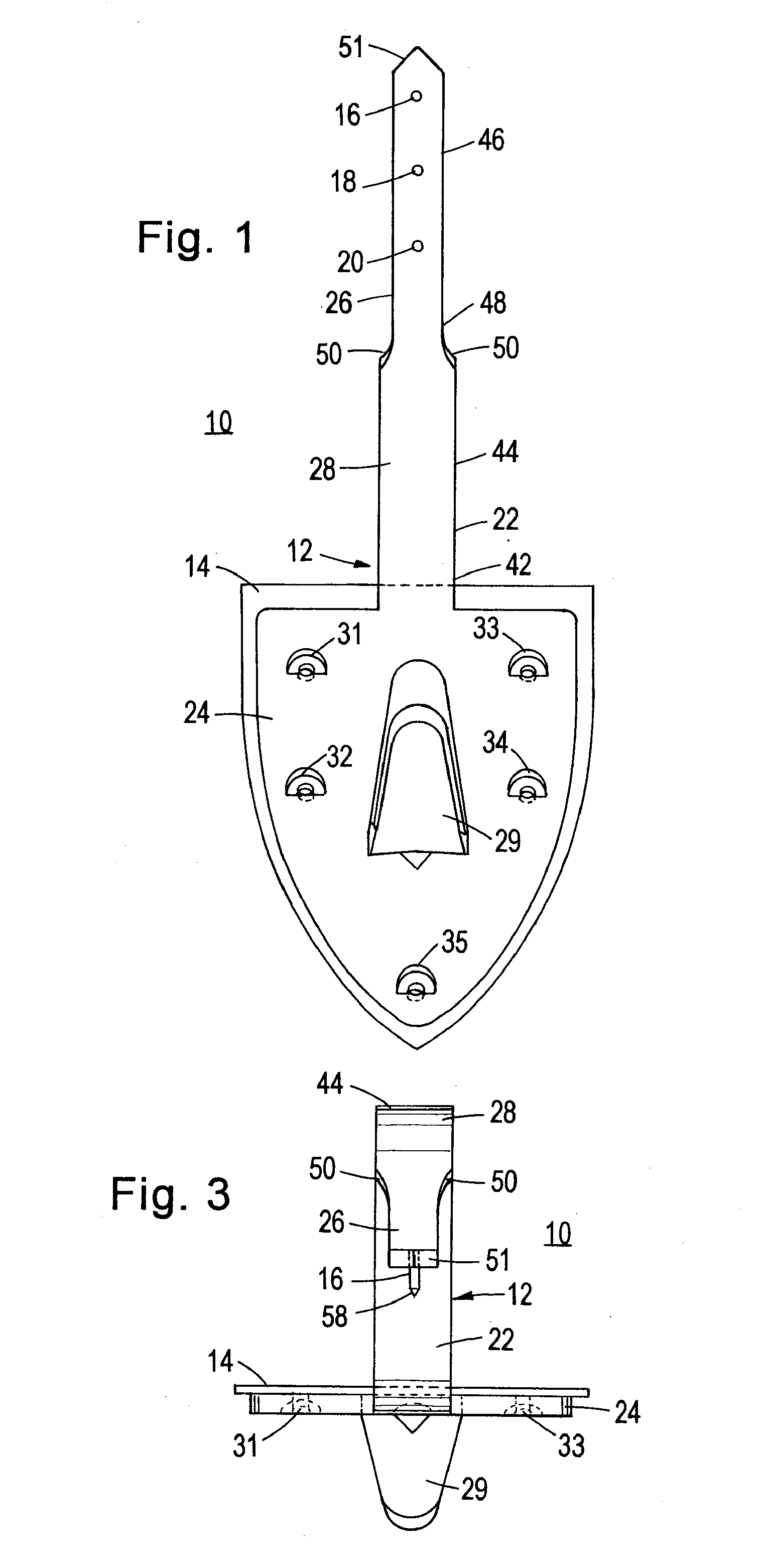
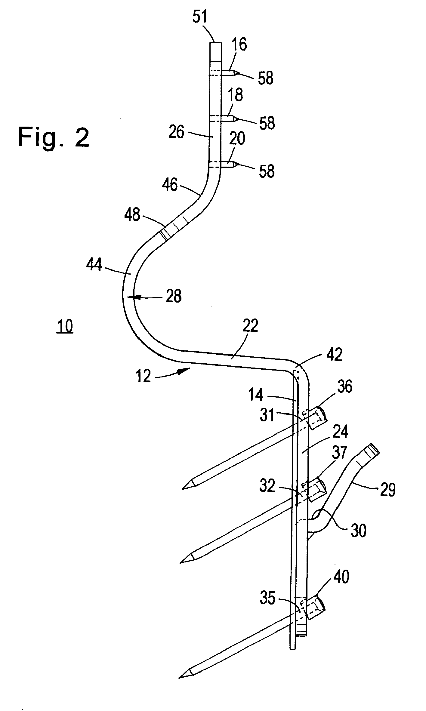
[0031]Reference is now made to FIGS. 1-5, drawings of an uninstalled picture hanger 10 found, through experimentation, to hold loads up to 280 pounds (127.3 kg) on a ⅝ inch (1.59 cm) thick drywall wall. Picture hanger 10 consists of one-piece sheet metal structure 12, shock absorbing layer 14, and nails 16, 18 and 20. Shock absorbing layer 14 and nails 16, 18 and 20 are fixedly attached to sheet metal structure 12 that includes planar shoulder 22, planar leg 24, planar arm 26 and arcuate spring 28. In a preferred embodiment, structure 12 is made of 12 gauge (0.109 inch (2.77 mm) thick) low carbon steel coated with brass plating. After a sheet metal blank that is to form structure 12 has been extruded, the blank is stamped and formed to the shape described infra.

[0032]When hanger 10 is installed on the drywall wall, shoulder 22 extends generally horizontally through a horizontal hole in the wall, between front and back faces of the wall. Leg 24 is c...


PUM


Abstract

A wallboard wall carries a picture or shelf hanger in a hole between front and back faces of the wall. The hanger includes: a one-piece member having (a) a shoulder having a bottom portion bearing against a bottom portion of the hole and extending horizontally through the hole, (b) an arm extending upwardly from the shoulder, (c) a leg (i) extending downwardly from the shoulder, and (ii) located outside the front face of the wall and (d) a load bearing surface for receiving the object. The arm has a sharp pointed end piercing the back face of the wall and extending into the wall via the back face of the wall.

Description

FIELD OF INVENTION[0001]The present invention relates generally to hangers for hanging objects on wallboard walls, and more particularly to such a hanger having a shoulder that extends horizontally through a hole in the wall and includes an arm having a sharp pointed end that pierces the back face of the wall and extends into the wall via the back face.BACKGROUND ART[0002]Skorka, U.S. Pat. No. 6,695,276 and US Patent Publication 2004 / 0159766 disclose wall hanger assemblies comprising a clip having a shoulder that extends through a horizontal hole in a drywall wall. (The term drywall is synonymous with the terms wallboard, gypsum board, plasterboard and is known by other names throughout the world.) An arm extends upwardly from the shoulder to abut and engage the interior face of the wall, and seat against the interior face. A leg carrying a hook extends downwardly from the shoulder in front of the exterior face of the wall. Prior to inserting the arm and shoulder through the hole a ...

Claims


Application Information

Patent Timeline
IPC IPC(8): A47B96/06
CPCA47G1/20A47G1/205A47G1/1633A47G1/22
Inventor MEJIA, EDSONTANGER, JONATHAN PAULWECK, DAVIDBERENSON, STEVEN C.
Owner THE HILLMAN GRP INC
Why Eureka
Try Eureka