Magnetic field sensing device

a sensing device and magnetic field technology, applied in the direction of measurement devices, magnetic measurements, instruments, etc., can solve the problems of large reset pulses from bulky coils of approximately 10 ma, high cost of amr sensor configuration,

a sensing device and magnetic field technology, applied in the direction of measurement devices, magnetic measurements, instruments, etc., can solve the problems of large reset pulses from bulky coils of approximately 10 ma, high cost of amr sensor configuration,

US20100213933A1Active Publication Date: 2010-08-26EVERSPIN TECHNOLOGIES

Image

  • Magnetic field sensing device
  • Magnetic field sensing device
  • Magnetic field sensing device

Examples


Embodiment Construction

[0014]The following detailed description of the invention is merely exemplary in nature and is not intended to limit the invention or the application and uses of the invention. Furthermore, there is no intention to be bound by any theory presented in the preceding background of the invention or the following detailed description of the invention.

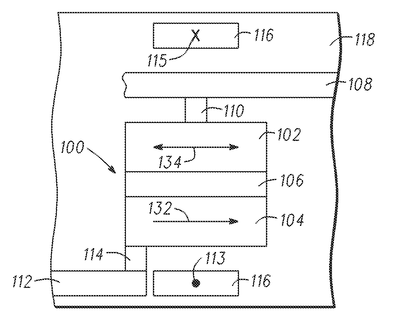
[0015]Small footprint magnetic sensors typically are laid out in a Wheatstone bridge configuration, where a precise balance between the resistances of the circuit elements must be maintained for the bridge to produce a minimal response in a zero magnetic field. Any nonzero response (bridge offset) present from the manufacturing process must be calibrated or nulled out to produce signals that are free from error. These offsets may shift over the lifetime of the part, in response to temperature changes, mechanical stresses, or other effects. In a compass application with a typical field response of 1.0 to 5.0 mV / V / Oe, maintaining an accuracy o...


PUM


Abstract

A magnetic field sensing device for determining the strength of a magnetic field, includes four magnetic tunnel junction elements or element arrays (100) configured as a bridge (200). A current source is coupled to a current line (116) disposed near each of the four magnetic tunnel junction elements (100) for selectively supplying temporally spaced first and second currents. Sampling circuitry (412, 414) coupled to the current source samples the bridge output during the first and second currents and determines the value of the magnetic field from the difference of the first and second values. A method for sensing the magnetic field includes supplying a first current to the current line (116), supplying a second current the current line (116), sampling the value at the output for each of the first and second currents, determining the difference between the sampled values during each of the first and second currents, and determining a measured magnetic field based on the determined difference.

Description

FIELD OF THE INVENTION[0001]The present invention generally relates to a magnetic field sensing device and more particularly to a magnetic tunnel junction device capable of accurately sensing small magnetic fields.BACKGROUND OF THE INVENTION[0002]Sensors are widely used in modern systems to measure or detect physical parameters, such as position, motion, force, acceleration, temperature, pressure, etc. While a variety of different sensor types exist for measuring these and other parameters, they all suffer from various limitations. For example, inexpensive low field sensors, such as those used in an electronic compass and other similar magnetic sensing applications, generally comprise anisotropic magnetoresistance (AMR) based devices. In order to arrive at the required sensitivity and reasonable resistances that mesh well with CMOS, the sensing units of such sensors are generally in the order of square millimeters in size. Furthermore, large reset pulses from bulky coils of approxim...

Claims


Application Information

Patent Timeline
26 Aug 2010
Publication
US20100213933A1
IPC
G01R33/09
CPC
G01R33/098; G01R33/05
Inventors
MATHER, PHILLIP G.; SLAUGHTER, JON M.