
Battery pack and over-discharge protecting method thereof

Active Publication Date: 2010-08-26
SAMSUNG SDI CO LTD
View PDF18 Cites 14 Cited by
  • Summary
  • Abstract
  • Description
  • Claims
  • Application Information

AI Technical Summary

Benefits of technology

[0008]Exemplary embodiments of the present invention provide a battery pack, which can automatically blow out a fuse when the battery pack is left in an over-discharged state for a long time or in an overcharged state, thereby preventing an accident from happening due to the battery pack exploding or igniting.
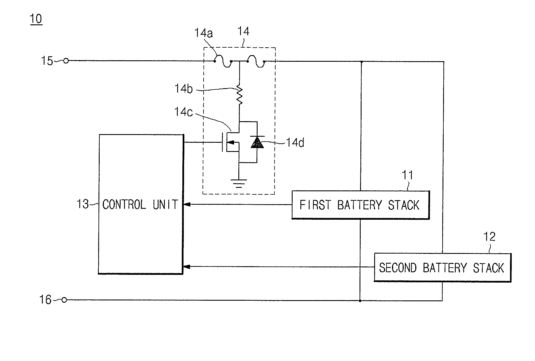
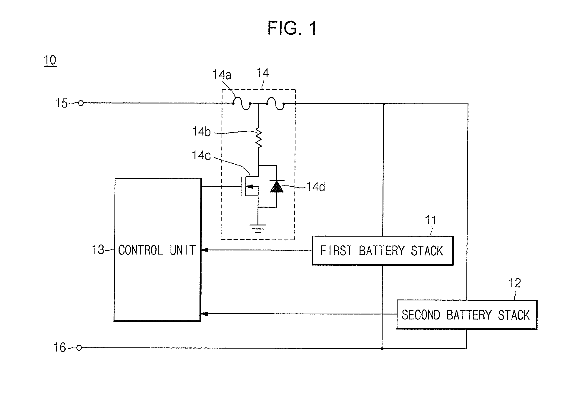
[0018]The fuse blowing unit may further include a diode to prevent electric noise from flowing into the controller.
[0026]As described above, the battery pack according to an embodiment of the present invention is configured such that if the battery pack is left in the over-discharged state for a long time or in an overcharged state for a long time, the fuse is blown out to prohibit a user from using the battery pack. That is, even though the battery pack is connected to a charger by the user, it is not charged. In other words, if the battery pack is over-discharged enough to elute a copper therefrom, the battery pack according to the present invention blows out the fuse, such that the battery pack is not charged even though it is connected to the charger. In addition, if the battery pack is overcharged beyond a reference voltage, the battery pack according to an embodiment of the present invention blows the fuse. Therefore, the battery pack is prevented from exploding or igniting, for example.

Problems solved by technology

That is, the cooper is eluted from the negative electrode collector, so that a negative electrode and a positive electrode are electrically connected to or with each other, thereby causing a short circuit.
Under this state, if the battery cell or / and pack begins to charge, a large amount of heat may be generated between the negative electrode and the positive electrode, which are short-circuited, and thus the battery cell and / or pack may explode or ignite.

Method used


Image

  • Battery pack and over-discharge protecting method thereof
  • Battery pack and over-discharge protecting method thereof
  • Battery pack and over-discharge protecting method thereof

Examples


Embodiment Construction

[0037]In the following detailed description, only certain exemplary embodiments of the present invention are shown and described, by way of illustration. As those skilled in the art would recognize, the invention may be embodied in many different forms and should not be construed as being limited to the embodiments set forth herein. Like reference numerals designate like elements throughout the specification.

[0038]FIG. 1 is a schematic block diagram of a battery pack according to an embodiment of the present invention.

[0039]As illustrated in FIG. 1, the battery pack 10 according to one embodiment of the present invention includes a first battery stack 11, a second battery stack 12, a control unit 13 (i.e., a controller), and a fuse blowing unit 14.

[0040]The first battery stack 11 includes a plurality of battery cells connected in series or in parallel.

[0041]The second battery stack 12 includes a plurality of battery cells connected in series or in parallel. In addition, the second b...


PUM


Abstract

A battery pack includes a first battery stack having a plurality of battery cells connected in series, a second battery stack having a plurality of battery cells connected in series and connected in parallel to the first battery stack, a controller for sensing voltages of the plurality of battery cells of the first battery stack and the plurality of battery cells of the second battery stack and for outputting a fuse blowing signal when at least one of the sensed voltages is lower than a first reference voltage, and a fuse blowing unit for electrically decoupling the first and second battery stacks from an output terminal of the battery pack in response to the fuse blowing signal from the controller. A fuse blowing signal is also sent to the fuse blowing unit when the at least one of the sensed voltages is higher than a second reference voltage.

Description

BACKGROUND OF THE INVENTION[0001]1. Field of the Invention[0002]The present invention relates to a battery pack and a protection method thereof.[0003]2. Description of the Related Art[0004]In general, a battery pack includes a plurality of battery cells, a charging switch to prevent the battery cells from being overcharged, a discharging switch to prevent the battery cells from being over-discharged and a control unit to control the charging switch and the discharging switch.[0005]The control unit senses voltages of the battery cells, so that it turns off the charging switch to stop charging if the battery cells are overcharged and the discharging switch to stop discharging if over-discharged.[0006]If the battery pack is left alone for a long time, it continues to decrease in voltage due to a self-discharging phenomenon that discharges on its own by three to five percents each month, even though the discharging switch is turned on to stop discharging. For instance, in a lithium-ion ...

Claims


Application Information

Patent Timeline
IPC IPC(8): H02H3/24H01M2/34H02J7/00
CPCH02J7/0013H02J2007/004H02J7/0031H02J7/0026H02J7/00306
Inventor YUN, CHANGYONG
Owner SAMSUNG SDI CO LTD
Learn More