Electrode plate for a battery

a technology of electrode plate and battery, applied in the direction of positive electrode, cell components, electrochemical generators, etc., can solve the problems of easy manufacturing, space waste, performance suffer, etc., and achieve the effect of high electroactivity, low cost, and high performance structur

Inactive Publication Date: 2010-08-26
FIREFLY INT ENERGY CO
View PDF14 Cites 5 Cited by
  • Summary
  • Abstract
  • Description
  • Claims
  • Application Information

AI Technical Summary

Benefits of technology

[0007]The invention is an electrode plate apparatus and method of manufacturing that maintains a thickness of electroactive paste between the electrode and the electrolyte that is small enough to maintain high electroactivity, by eliminating the areas of less effective active material paste in the space in the center of each pellet. The present invention supplements currently widespread manufacturing techniques for a lower cost implementation of higher performance structures.

Problems solved by technology

The areas of low electroactivity 20 add weight to the battery without adding power or capacity, and were effectively wasted space in that regard.
First, it was easy to manufacture.
Hence, for the sake of structural strength, simplicity and manufacturing expedience, performance suffered.

Method used


Image

  • Electrode plate for a battery
  • Electrode plate for a battery
  • Electrode plate for a battery

Examples


Embodiment Construction

[0020]The following description of the preferred embodiment(s) is merely exemplary in nature and is in no way intended to limit the invention, its application, or uses.

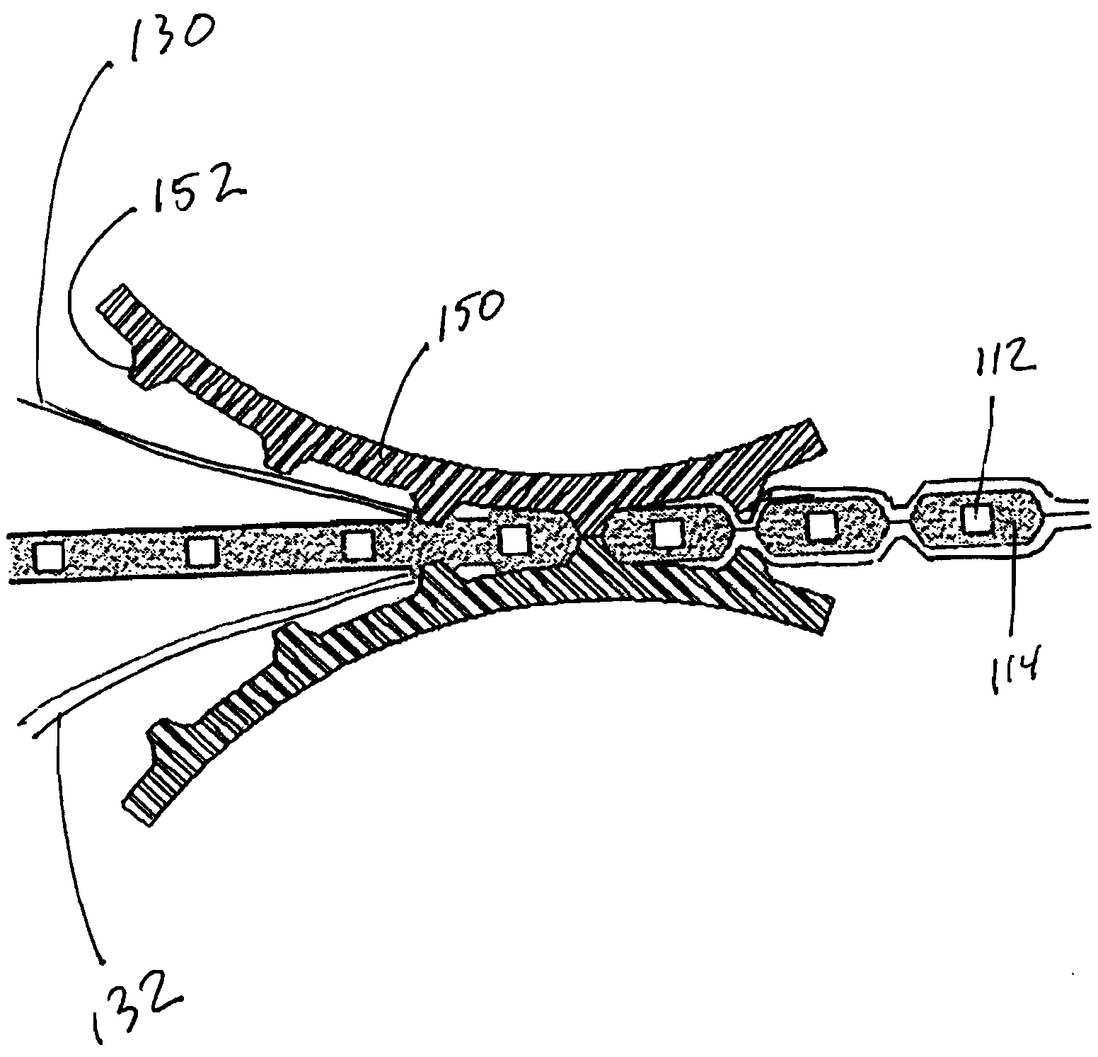
[0021]FIG. 3 is a cross section of the structure of the positive plate of the present invention. In it are shown electrodes 112. They are completely surrounded by and embedded in active material paste 114. However, an area 120 between the grids has a narrowed thickness of active material paste or no active material paste at all, thereby comprising a hole 124.

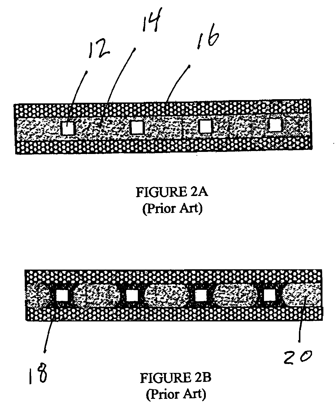
[0022]FIG. 3 depicts the structure of a positive plate after assembling into a battery. According, liquid electrolyte 116 can be seen surrounding the plate structure. The plate having been manufactured with narrowed pellet centers or holes 120, upon assembly the electrolyte enters these spaces. As is evident, spaces that in the prior art structures have been areas of low electroactivity (20 in FIG. 2B), have been eliminated. The space left by hole 120 is now fille...


PUM

PropertyMeasurementUnit
porosityaaaaaaaaaa
thicknessaaaaaaaaaa
porosityaaaaaaaaaa

Abstract

An electrode plate for a battery comprising a plurality of electrodes in a grid where the grid defines a plurality of spaces. A paste disposed in the spaces has a top surface and a bottom surface. The paste is narrowed in the space, defining a distance between the top surface of the paste and the bottom surface of the paste that is less than the thickness of the plate over the electrodes. A retention layer of porous fabric is impressed on the top and/or bottom surface of the paste. Electrolyte disposed in electric communication with the electrodes.

Description

BACKGROUND OF THE INVENTION[0001]1. Field of the Invention[0002]The present invention is in the field of lead acid batteries, the structure of the plates for lead acid batteries and methods of manufacturing the same.[0003]2. RELATED ART[0004]Traditionally, lead acid batteries have included positive plates and negative plates that are immersed in electrolyte and sealed to make the battery. The plates are each made of essentially two elements. The two plate elements include a grid such as that depicted in FIG. 1 which was an electro-conductive material such as lead. This grid comprised an electrode. The plate was completed by embedding this grid in a paste which was a clay-like material in consistency and was electro-conductive. This positive active material (PAM) or negative active material (NAM) filled the spaces between the grid lines or electrodes. These spaces, when filled with paste, were referred to as pellets. Encasing the electrode grid in the paste also established a thin la...

Claims


Application Information

Patent Timeline
Patent Type & Authority Applications(United States)
IPC IPC(8): H01M4/74H01M4/82
CPCY02E60/126H01M4/82H01M2004/028H01M4/663H01M4/68H01M4/16Y10T29/49108H01M4/745H01M4/747H01M4/667H01M4/665H01M4/74H01M4/73Y02E60/10
Inventor KELLEY, KURTIS C.ALKHATEEB, MOHAMADKHEIR
Owner FIREFLY INT ENERGY CO
Why Eureka
Try Eureka