Power supply switch

Active Publication Date: 2010-09-02
MELTZNER INNOVATIONS
View PDF15 Cites 2 Cited by
  • Summary
  • Abstract
  • Description
  • Claims
  • Application Information

AI Technical Summary

Benefits of technology

[0010]In another embodiment of the present invention, the control circuit further includes a Transient Voltage Suppression (TVS) circuit. The TVS circuit operates to remove, or otherwise suppress transient voltages, e.g

Problems solved by technology

Despite the enormous advantages common appliances afford users, there are also disadvantages.
Such routine use of appliances often reduces the user's awareness of the operational state of the appliance.
Also, users are often distracted or otherwise inattentive to the appliance.
These fires resulted in an average dollar loss of $6,029 million.
Another concern when using appliances is the energy usage, and thus cost associated with use.
All electrical appliances consume energy.
Inattenti

Method used


Image

  • Power supply switch
  • Power supply switch
  • Power supply switch

Examples


Example

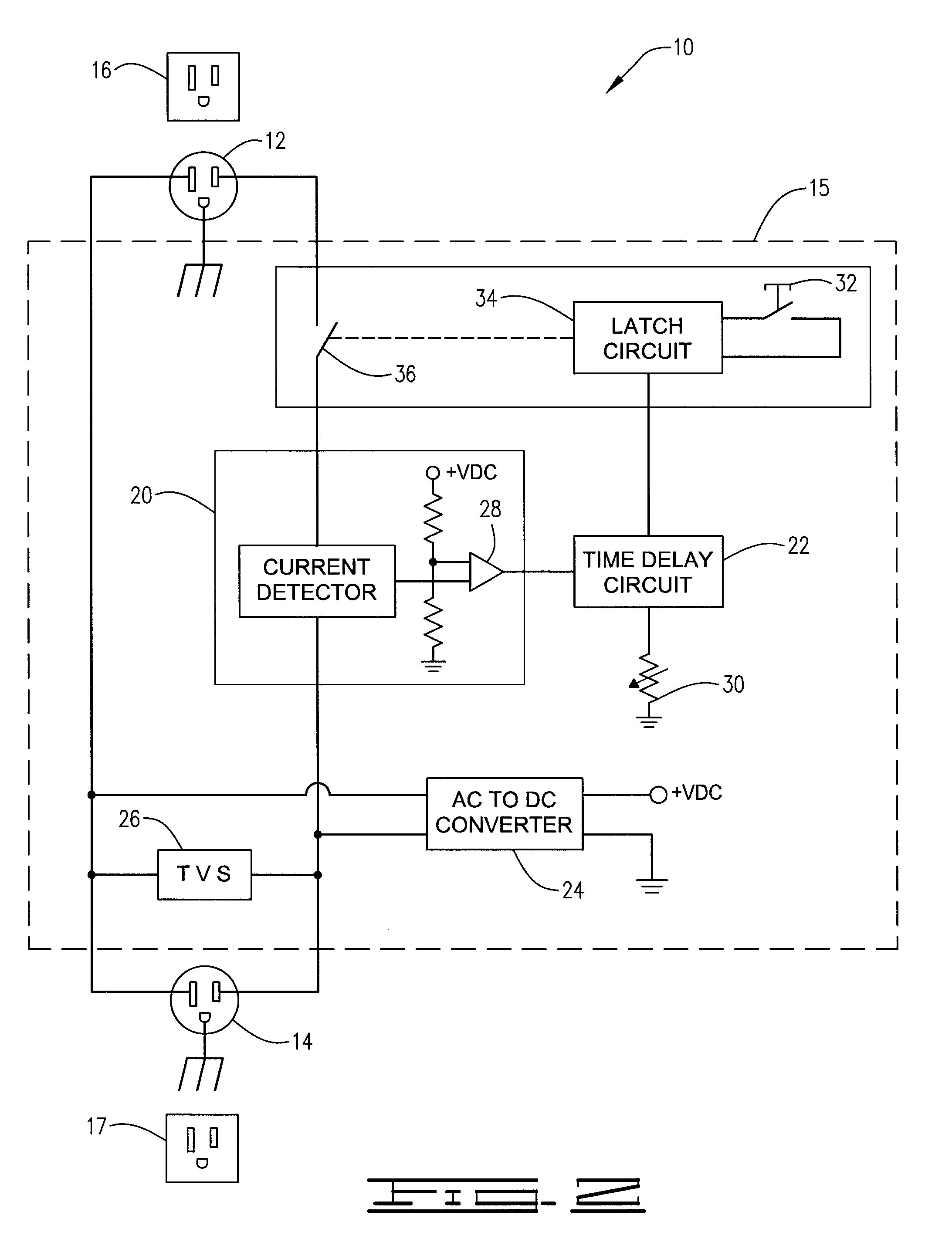
[0022]For example in a first embodiment as illustrated in FIG. 2, the switch 18 can be formed using a reset switch 32, a latch circuit 34 and a relay 36. In this first embodiment of the switch 18, the reset switch 32 is accessible to, and utilized by the user of the power supply switch 10 to activate the latch circuit 34 to place the relay 36 in the closed position. The latch circuit 34 is also configured to receive a signal from the timer circuit 22 and place the relay 36 in the open position in response thereto. The reset switch 32 can be implemented using a mechanical switch, electrical switch, a combination thereof or any equivalent which enables the user of the power supply switch 10 to manually reset the relay 36 of the switch 18 to the closed position.

[0023]The relay 36 can be implemented using a mechanical, solid state, combination thereof or any equivalent device which is capable of having an open position and a closed position and is able to be controlled by the latch circ...

Example

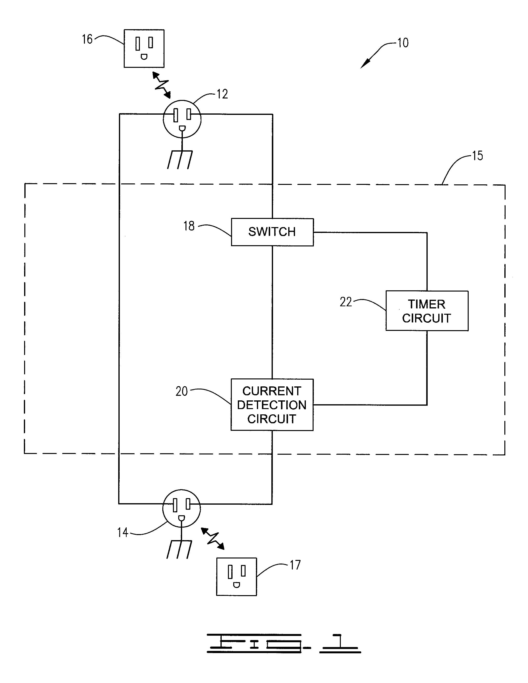
[0028]In a second embodiment of the present invention, the control circuit 15 can also be implemented using a micro-controller, microprocessor or the like in conjunction with a current sensing device, as described above, and a switch as is also described above. In this embodiment, the switch 18, current detection circuit 20 and timer circuit 22, or portions of each circuit can be implemented using a single microcontroller. For example, the current detection circuit 20 would utilize a sensing method previously described to sense current passing through the power supply switch 10. In this embodiment, the sensing method would output a signal indicative of the sensed circuit to an analog-to-digital function commonly found in micro-controller devices. The micro-controller could perform all, or at least many of the functions previously described with regards to the timer circuit 22, current detection circuit 20 and the latch circuit 34.

[0029]Also described herein is a method of automatica...


PUM


Abstract

A power supply switch comprising a power input assembly receiving power from a power source, a power output assembly connected to an appliance and a control circuit between the power input assembly and power output assembly. The control circuit comprises a switch having an open position and a closed position and being manually resettable by a user to the closed position, wherein power is supplied from the power input assembly to the power output assembly when the switch is in the closed position; a current detection circuit sensing a current passing from the power input assembly to the power output assembly, the current detection circuit outputting an activation signal indicative of the presence of the sensed current; and a timer circuit receiving the activation signal and automatically activating a timer in response, wherein the timer sends a signal to the switch causing the switch to move to the open position after a delay time.

Description

CROSS-REFERENCE TO RELATED APPLICATIONS[0001]Not ApplicableBACKGROUND OF THE INVENTION[0002]Electrical appliances have become a vital part of virtually every household and business. Common electrical appliances include curling irons, flat irons, hair dryers, air compressors, electric tools, coffee pots, electric cookers, electric blankets, heating pads, computers and the like. Most common electrical appliances are used by homeowners each and every day and often are an important tool used in the home and / or business. Despite the enormous advantages common appliances afford users, there are also disadvantages. Such routine use of appliances often reduces the user's awareness of the operational state of the appliance. Also, users are often distracted or otherwise inattentive to the appliance.[0003]A large percentage of household fires are attributable to inattentive use of electrical appliances. Frequently, such fires are caused by appliances that generate heat, i.e., hair dryers, curl...

Claims


Application Information

Patent Timeline
IPC IPC(8): H01H83/00
CPCH01H43/02
Inventor MELTZNER, JAMIE H.
Owner MELTZNER INNOVATIONS
Why Eureka
Try Eureka