Information processing apparatus, control method, and program

a technology of information processing apparatus and control method, applied in the direction of digital output to print units, instruments, computing, etc., can solve the problems of reducing the print processing speed, and achieve the effect of saving print data, improving user friendliness, and reducing the job sending speed

Inactive Publication Date: 2010-09-02
CANON KK
View PDF7 Cites 19 Cited by
  • Summary
  • Abstract
  • Description
  • Claims
  • Application Information

AI Technical Summary

Benefits of technology

[0011]The present invention has been made to overcome the conventional drawbacks, and provides a system which holds job data without the influence of a changed processing order or the like upon deleting or suspending a job, and does not decrease the printing speed when different printing control apparatuses simultaneously request a plurality of print processes of a single printing apparatus.
[0014]With this arrangement, print data can be saved even when a client computer deletes a job and a printing apparatus does not print.
[0015]When suspending sending of a job, print data can be saved without waiting for the sending of the job. When printing is executed after suspending the job, the job need not be archived again, improving user friendliness. After resuming the sending of the job, the job can be sent without decreasing the job sending speed.
[0016]If the attribute of print data of a job archived in advance is changed, the attribute-changed job can be saved. A job with finally printed data can be archived.
[0017]Accordingly, the present invention can provide a system which does not limit the specifications of a printing control apparatus, holds data without leaking the held data, and does not decrease the printing speed even if a plurality of printing control apparatuses with different processing purposes run simultaneously and request print processes of a single printing apparatus.

Problems solved by technology

However, when these two systems are simply applied to one printing control system simultaneously, they may cause an error.
For example, when a port monitor has a print data copy function and performs copy processing and save processing in sending print data, the sending of print data cannot be completed till the end of copying the print data, which may decrease the print processing speed.

Method used


Image

  • Information processing apparatus, control method, and program
  • Information processing apparatus, control method, and program
  • Information processing apparatus, control method, and program

Examples


first embodiment

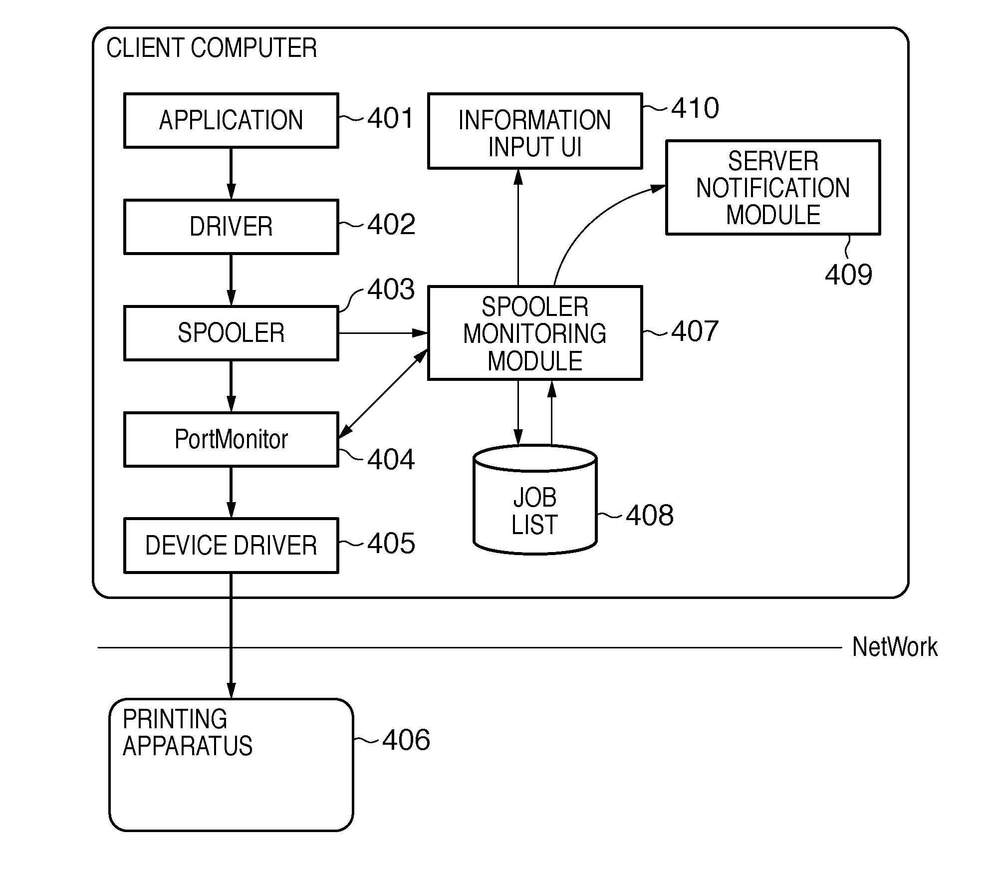
[0064]The first embodiment will be explained with reference to FIGS. 9, 10, 11, 12, 13, 14, and 15. FIGS. 9 to 12 show a series of divided sequences. Main processors (spooler, port monitor, printing apparatus, spooler monitoring module, and archive module) in FIGS. 6 to 8 cope with FIGS. 9 to 15.

[0065]FIG. 9 is a flowchart exemplifying the basic operation of the port monitor according to the first embodiment. For descriptive convenience, the port monitor automatically starts upon activation of the spooler system on Microsoft Windows®, and automatically ends at the end of the spooler system. The port monitor is assumed to adopt print monitor functions laid open to the public by MSDN (Microsoft Developer Network)®. In S901, the port monitor determines a function called by the spooler. If the function is a public function StartDoc( ), the process advances to sequence (A) in FIG. 10 to perform processing at the start of a job. If the port monitor determines in S901 that the function is ...

second embodiment

[0082]The second embodiment will be explained with reference to FIGS. 9, 13, 14, 15, 16, 17, and 18. The first embodiment has described a printing history management system which deletes a job. The second embodiment will examine application of the present invention to a system which stops execution of a job without deleting it when the number of jobs has exceeded the upper limit value of jobs processible for a given user. A description common to the first embodiment will not be repeated, and only a difference will be explained. The second embodiment is different from the first embodiment in the sequences of FIGS. 16, 17, and 18. Similar to the first embodiment, main processors (spooler, port monitor, printing apparatus, spooler monitoring module, and archive module) in FIGS. 6 to 8 also cope with FIGS. 16 to 18.

[0083]FIG. 16 is a flowchart exemplifying the basic operation of the port monitor at the start of a job according to the second embodiment. This sequence corresponds to FIG. ...

third embodiment

[0088]The third embodiment will be explained with reference to FIGS. 9, 13, 14, 15, 18, 19, and 20. The second embodiment has described a printing history management system which suspends a job. The third embodiment will examine application of the present invention to a system which changes an attribute, for example, forcibly changes single-sided printing to double-sided printing by correcting job data. A description common to the second embodiment will not be repeated, and only a difference from the second embodiment will be explained. The third embodiment is different from the second embodiment in the sequences of FIGS. 19 and 20. Similar to the second embodiment, main processors (spooler, port monitor, printing apparatus, spooler monitoring module, and archive module) in FIGS. 6 to 8 also cope with FIGS. 19 and 20.

[0089]FIG. 19 is a flowchart exemplifying the basic operation of the port monitor at the start of a job according to the third embodiment. In S1901, the port monitor in...


PUM


Abstract

An information processing apparatus includes a spooler for spooling jobs received from an application; a spooler monitor; an archive unit for archiving a job; and a port monitor; the port monitor being configured to: detect if the spooler starts a job, in a case that the port monitor detects that the spooler starts a job, request control parameters from the spooler monitor and archive unit; and in a case that a control parameter received from the archive unit indicates that the job is to be archived, and a control parameter received from the spooler monitor indicates that another operation is to be performed on the job, cause the archive unit to archive the job and cause performance of the other operation.

Description

BACKGROUND OF THE INVENTION[0001]1. Field of the Invention[0002]The present invention relates to an information processing apparatus, control method, and program. Particularly, the present invention relates to save of job data of a spooled job.[0003]2. Description of the Related Art[0004]These days, copying apparatuses and printing apparatuses have prevailed in the offices of companies and the like, and allow anyone to copy and print easily. This situation causes problems such as security problems typified by leakage of printed materials of in-house documents, wasteful printing, and printed material left after output by an unknown user. To solve these problems, a printing history management system has been proposed to aggregate a printed document name, printing date & time, the number of sheets, the number of copies, color / monochrome printing, and the like in each print processing for each user.[0005]The printing history management system associates management information (e.g., cus...

Claims


Application Information

Patent Timeline
Patent Type & Authority Applications(United States)
IPC IPC(8): G06F3/12
CPCG06F3/1203G06F3/1219G06F3/1222G06F3/1239G06F3/1285G06F3/1267G06F3/1273G06F3/1274G06F3/126
Inventor SUGIYAMA, HIDEKI
Owner CANON KK
Why Eureka
Try Eureka