Led module and led light source apparatus

a technology of led light source and led module, which is applied in the direction of lighting and heating apparatus, lighting support devices, instruments, etc., can solve the problem of longer wires and achieve the effect of simple wire structur

Active Publication Date: 2010-09-02
SHARP KK
View PDF2 Cites 44 Cited by
  • Summary
  • Abstract
  • Description
  • Claims
  • Application Information

AI Technical Summary

Benefits of technology

[0022]The above characterized LED light source apparatus can provide a simple wire structure where external wires between LED modules and the control substrate or between LED modules can be much shorter.

Problems solved by technology

The smaller the LED modules are relative to the area illuminated by the light source apparatus, and the greater the number of LED modules used is, the longer the wires become, and the more problems there are with mounting the modules.
However, a problem arises, such that various types of LED modules must be prepared in accordance with the area to be illuminated by the light source apparatus.

Method used


Image

  • Led module and led light source apparatus
  • Led module and led light source apparatus
  • Led module and led light source apparatus

Examples


first embodiment

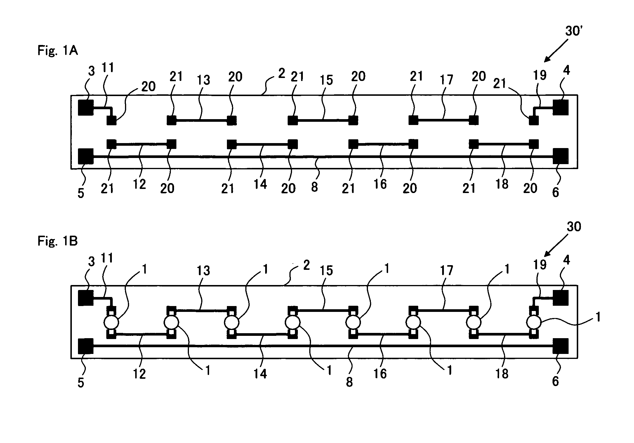
[0054]FIG. 1 is a schematic diagram showing the structure of the LED module according to the first embodiment of the present invention. FIG. 1A shows a printed wiring board 30′ before LEDs are mounted, and FIG. 1B shows an LED module 30 after LEDs 1 have been mounted.

[0055]A printed wiring board 30′ comprises an insulating substrate 2 on which nine connecting wires 11 to 19 for connecting eight LEDs 1 in series, four terminals including a first main terminal 3, a second main terminal 4, a first sub-terminal 5 and a second sub-terminal 6 for the connection to an external circuit and a first passing wire 8 for electrically connecting the first sub-terminal 5 to the second sub-terminal 6 are formed. The insulating substrate 2 is formed of an insulating material, such as glass epoxy, and the connecting wires 11 to 19, the four terminals 3 to 6 and the first passing wire 8 are formed of a metal film, such as a copper foil.

[0056]The connecting wires 11 to 19 are aligned side by side at a ...

second embodiment

[0067]Next, the LED module according to the second embodiment of the present invention is described. FIG. 6 schematically shows the structure of the LED module according to the second embodiment of the present invention. FIG. 6A shows a printed wiring board 31′ before LEDs are mounted, FIG. 6B shows an LED module 31 (31a) after LEDs 1 have been mounted, and FIG. 6C shows an LED module 31 (31b) after LEDs 1 and a short-circuit element 22 have been mounted.

[0068]A printed wiring board 31′ comprises an insulating substrate 2 on which nine connecting wires 11 to 19 for connecting eight LEDs 1 in series, electrodes 20 and 21, four terminals including a first main terminal 3, a second main terminal 4, a first sub-terminal 5 and a second sub-terminal 6 for the connection to an external circuit, a first passing wire 8 for electrically connecting the first sub-terminal 5 to the second sub-terminal 6, an electrode 23 for an electrical connection to the connecting wire 19 (corresponding to sec...

third embodiment

[0075]Next, the LED module according to the third embodiment of the present invention is described. FIG. 9 schematically shows the structure of the LED module according to the third embodiment of the present invention. In the second embodiment, the electrode 23 is provided so as to be electrically connected to the connecting wire 19 (corresponding to the second connecting wire) and formed in close proximity to the electrode 24 electrically connected to the first passing wire 8, as shown in FIG. 6, while in the third embodiment, the electrode 23 is provided so as to be electrically connected to the connecting wire 11 (corresponding to first connecting wire), as shown in FIG. 9. FIG. 9A shows a printed wiring board 32′ before LEDs are mounted, FIG. 9B shows an LED module 32 (32a) after LEDs 1 have been mounted, and FIG. 9C shows an LED module 32 (32b) after LEDs 1 and a short-circuit element 22 have been mounted.

[0076]The printed wiring board 32′ in the third embodiment is different f...


PUM


Abstract

An LED module comprises: an insulating substrate in plate form; first main and sub terminals for connection to an external circuit formed near the first side of the insulating substrate; second main and sub terminals for connection to an external circuit formed near the second side opposite to the first side; three or more connecting wires formed on the insulating substrate for connecting LEDs continuously aligned at a distance from each other in series; LEDs individually connected between the connecting wires adjacent to each other and connected in series in a same direction; and a first passing wire formed on the insulating substrate for electrically connecting the first sub-terminal to the second sub-terminal, wherein a first connecting wire located on one side is electrically connected to the first main terminal, and a second connecting wire located on the other side is electrically connected to the second main terminal.

Description

CROSS REFERENCE TO RELATED APPLICATION[0001]This Nonprovisional application claims priority under 35 U.S.C. § 119(a) on Patent Application No. 2009-045120 filed in Japan on 27 Feb. 2009 the entire contents of which are hereby incorporated by reference.BACKGROUND OF THE INVENTION[0002]1. Field of the Invention[0003]The present invention relates to an LED module in which LEDs (light emitting diodes) are mounted, as well as an LED light source apparatus.[0004]2. Description of the Related Art[0005]Transmission type liquid crystal displays are provided with a backlight apparatus on the rear of the liquid crystal panel as a light source. Though conventional light sources for light source apparatuses used as a backlight are mainly CCFLs (cold cathode fluorescent lamps), LEDs have been expected to be used more and more as a light source instead of CCFLs as the technology develops. Japanese Unexamined Patent Publication 2003-207780, for example, (hereinafter referred to as Document 1) descr...

Claims


Application Information

Patent Timeline
Patent Type & Authority Applications(United States)
IPC IPC(8): F21S4/00
CPCF21K9/00F21S4/003H01L2924/19107G02F1/133603G02F1/13452F21Y2101/02H01L2224/05554H01L2224/48091H01L2224/48137H01L2224/49175F21S4/20F21Y2115/10H01L2924/00014
Inventor YAMASHITA, ATSUSHINABESAWA, HIROYUKINISHIOKA, HIROSHIWATANABE, MASAHIKOSUMITANI, KEN
Owner SHARP KK
Why Eureka
Try Eureka