Carrier Network Connection Device And Carrier Network

a network connection device and carrier technology, applied in the field of carrier backbone network connection devices and carrier backbone networks, can solve the problems of inability to solve the scalability problem of the existing mpls network, inability to use the infrastructure of the layer 3 routers configuring the mpls network, and inability to accept the replacement of the existing mpls backbone network with the new pbt network, etc., to achieve the effect of improving the scalability of the conventional

Inactive Publication Date: 2010-09-02
IP INFUSION INC
View PDF15 Cites 111 Cited by
  • Summary
  • Abstract
  • Description
  • Claims
  • Application Information

AI Technical Summary

Benefits of technology

[0023]According to the network connection device and the network having the above described configuration, it becomes possible to install additionally the layer 2...

Problems solved by technology

However, since PBT is a layer 2 network configured by Ethernet switches, it is impossible to use the infrastructure of the layer 3 routers configuring the MPLS network which is an existing large scale backbone IP network.
Although PBT is a low cost networ...

Method used


Image

  • Carrier Network Connection Device And Carrier Network
  • Carrier Network Connection Device And Carrier Network
  • Carrier Network Connection Device And Carrier Network

Examples


Embodiment Construction

[0061]In the following, an embodiment according to the present invention is described with reference to the accompanying drawings.

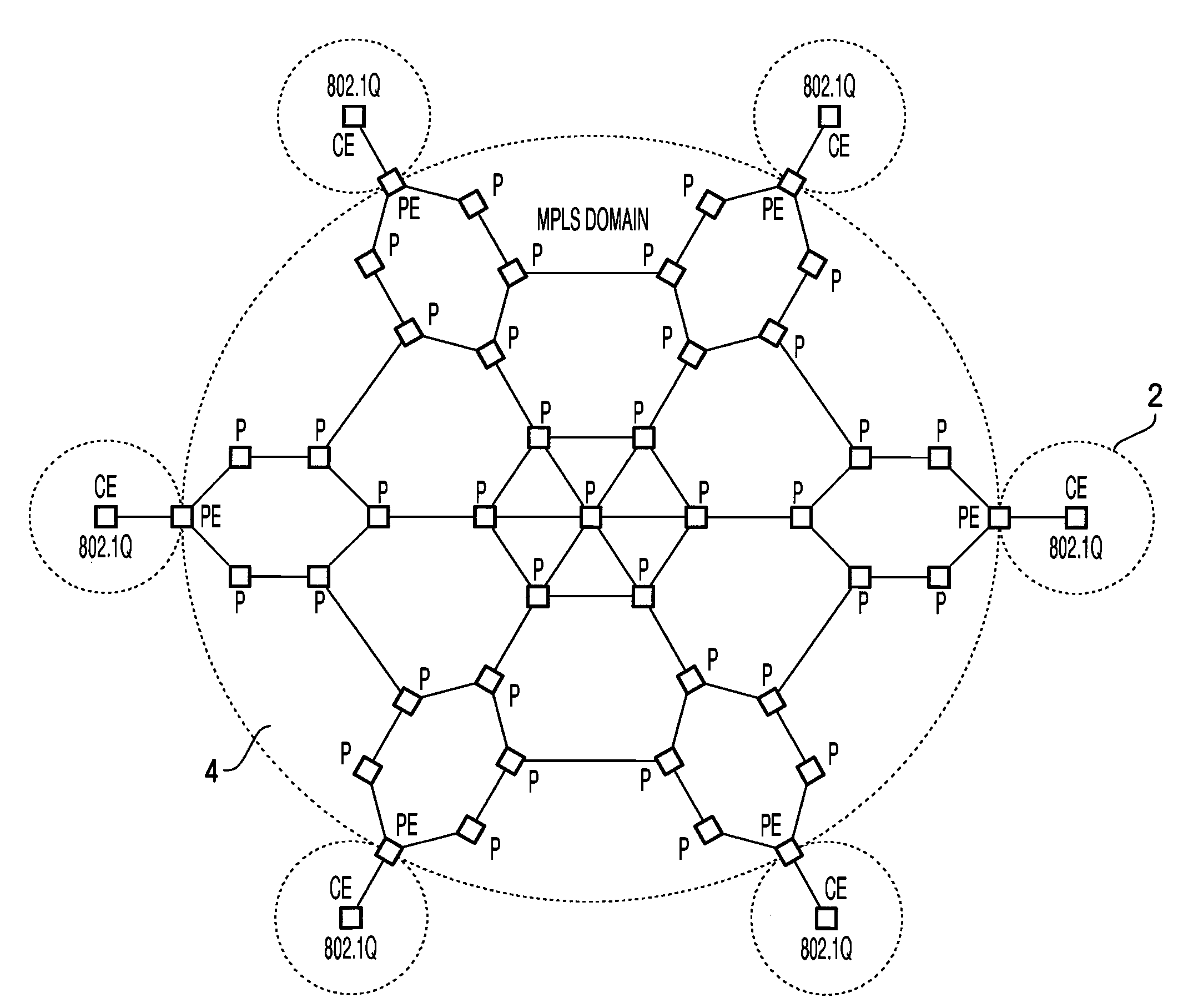
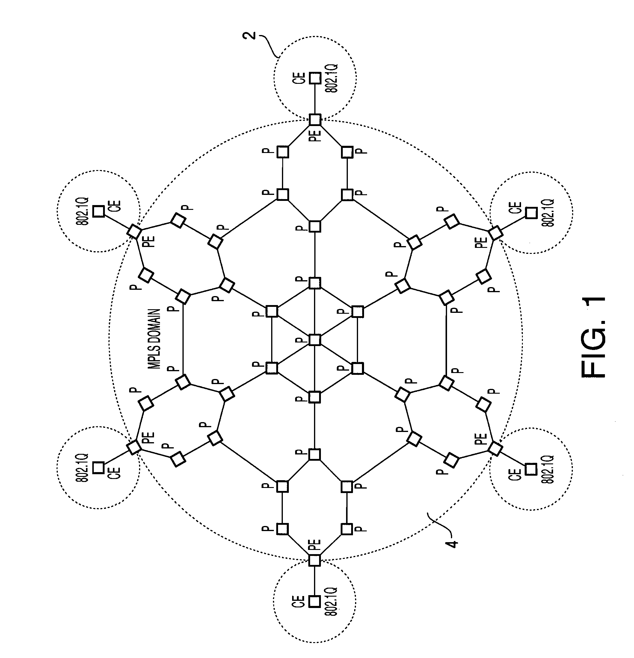
[0062]First, the entire configuration of a network system 1 according to an embodiment of the present invention is explained. FIG. 3 illustrates a topology of the network system 1. The network system 1 includes a carrier relay network PB having an MPLS domain 40 and a PBT domain 30, and a plurality of user networks 20.

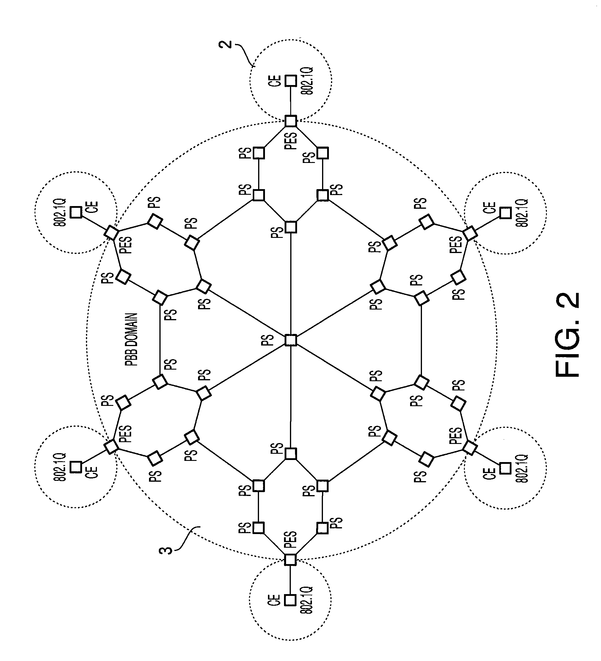
[0063]The MPLS domain 40 is a single domain layer 3 network integrated by MPLS routers transferring a packet based on a label. The PBT (PBB-TE) domain 30 is a single domain layer 2 network configured by Ethernet switches complying with PBT. Further, the user network 20 is a LAN (Local Area Network) configured by nodes, such as a personal computer PC, having a network interface card (NIC) complying with IEEE 802.1Q.

[0064]The carrier relay network PB has a structure where the periphery of the MPLS domain 40 is surrounded by the PBT domain 30. ...


PUM


Abstract

A network connection device connecting a pseudo wire of a layer 2 and a pseudo wire formed of a layer 3, comprising: a switching unit operating as an edge switch of a layer 2 network forming a first pseudo wire; a routing unit operating as an edge router of a layer 3 network forming a second pseudo wire; and a conversion unit which makes conversion between a frame of the layer 2 network and a packet of the layer 3 network.

Description

TECHNICAL FIELD[0001]The present invention relates to a carrier backbone network connection device and a carrier backbone network.BACKGROUND OF THE INVENTION[0002]MPLS (Multiprotocol Label Switching) defined in RFC3032 is widely known as an architecture to construct a carrier backbone network system. According to MPLS, a “label” having a short data length is assigned to a transfer packet, and the transfer packet is transferred between routers by referring the label for packet transferring. As a result, the router is not required to refer an IP header having a long data length, and it becomes possible to achieve a high speed routing. The label used in MPLS is assigned by exchanging routing information between MPLS routers using a protocol, such as LDP (Label Distribution Protocol). Furthermore, according to MPLS, VPN (Virtual Private Network), a hierarchical path, and etc. can be achieved by stacking a plurality of labels. Therefore, at present, MPLS is widely used in a large scale b...

Claims


Application Information

Patent Timeline
IPC IPC(8): H04L12/56
CPCH04L12/4633H04L12/4658H04L12/4662H04L45/68H04L45/50H04L45/66H04L45/00
Inventor ISHIGURO, KUNIHIRO
Owner IP INFUSION INC
Why Eureka
Try Eureka