Method and system for mapping environments containing dynamic obstacles

a mapping environment and dynamic obstacle technology, applied in the field of mapping environment with dynamic obstacles, can solve the problems of obstacles which were previously unobscured, obstacles that were partially or completely obscured, and the conventional detection unit cannot access every location of the environment,

Active Publication Date: 2010-09-02
TOYOTA MOTOR CO LTD
View PDF21 Cites 1 Cited by
  • Summary
  • Abstract
  • Description
  • Claims
  • Application Information

AI Technical Summary

Problems solved by technology

However, the conventional detection unit cannot access every location of the environment as obstacles frequently block one or more paths of the detection unit.
Furthermore, obstacles can be dynamic resulting in obstacles which were previously un-obscured, being partially or completely obscured.
The conventional detection unit, however, leaves the obstacle or portions of the obstacle in the map of the environment even when the obstacle has moved when the obstacles is partially or completely obscured.
This can lead to a number of obstacles appearing in the map of the environment which do not actually exist because they have since moved to a different location.
Thus, there is an unrecognized need for a more accurate method and system for mapping environments containing dynamic obstacles.

Method used


Image

  • Method and system for mapping environments containing dynamic obstacles
  • Method and system for mapping environments containing dynamic obstacles
  • Method and system for mapping environments containing dynamic obstacles

Examples


Embodiment Construction

[0023]Apparatus, systems and methods that implement the embodiments of the various features of the present invention will now be described with reference to the drawings. The drawings and the associated descriptions are provided to illustrate some embodiments of the present invention and not to limit the scope of the present invention. Throughout the drawings, reference numbers are re-used to indicate correspondence between referenced elements.

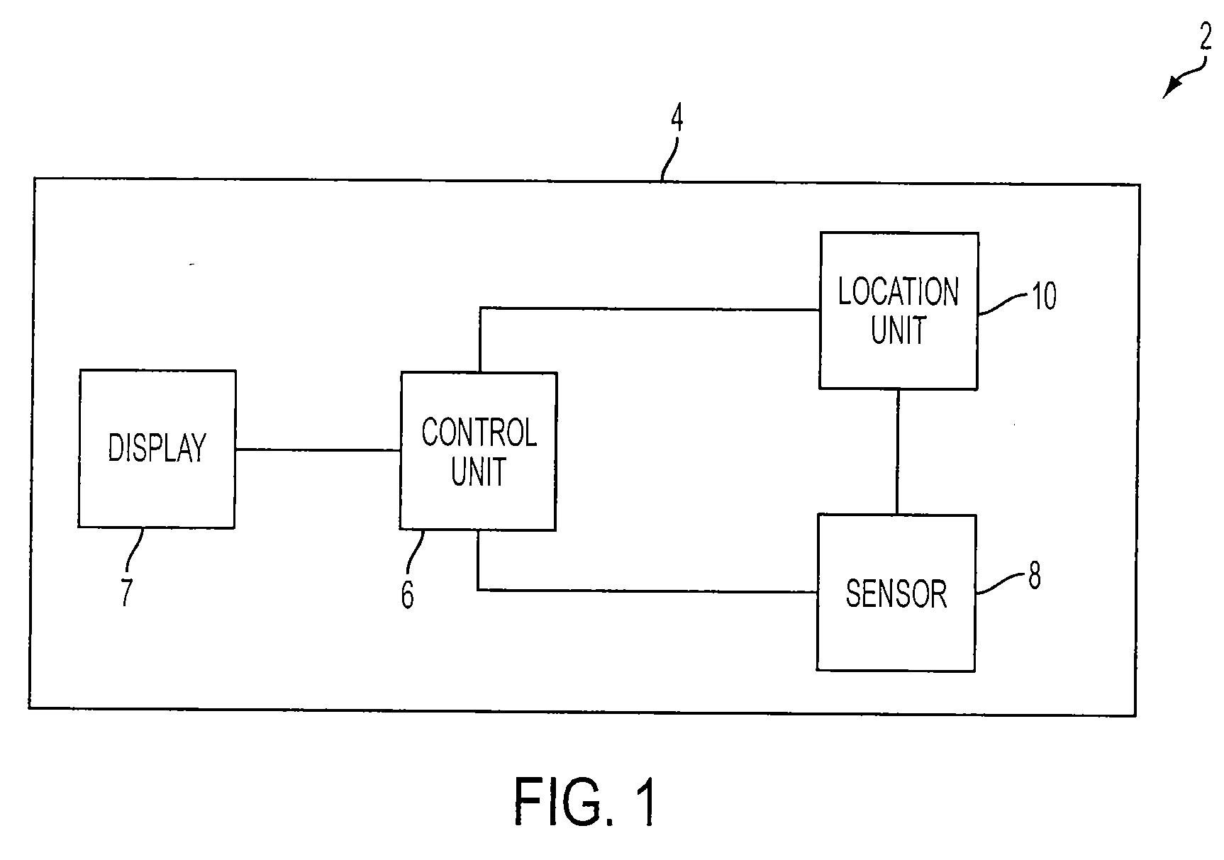
[0024]As seen in FIG. 1, a dynamic obstacle mapping system 2 includes a transportation unit 4. The transportation unit 4 can be, for example, an automobile, an airplane, a motorbike, a bicycle, or any other transportation devices. The transportation unit 4 includes a control unit 6, a display unit 7, a location unit 8 and a sensor 10.

[0025]The control unit 6 is connected to the location unit 8 and the sensor 10. The control unit 6 can be or include, for example, a central processing unit, a processor, a computer, an engine control unit, or any...


PUM


Abstract

The present invention relates to a method and system for mapping environments containing dynamic obstacles. In one embodiment, the present invention is a method for mapping an environment containing dynamic obstacles using a processor including the steps of forming a current instantaneous map of the environment, determining cells which are free space within the current instantaneous map, determining cells which are occupied space within the current instantaneous map, and integrating the current instantaneous map with an old integrated map of the environment to form a new integrated map of the environment.

Description

BACKGROUND[0001]1. Field[0002]The present invention relates to a method and system for mapping environments containing dynamic obstacles.[0003]2. Description of the Related Art[0004]When using a conventional detection unit to generate a map of an environment, the map plots where the obstacles are and where there are no obstacles in the environment. However, the conventional detection unit cannot access every location of the environment as obstacles frequently block one or more paths of the detection unit. Furthermore, obstacles can be dynamic resulting in obstacles which were previously un-obscured, being partially or completely obscured. The dynamic obstacles can also mean that obstacles which were previously present are now not present. The conventional detection unit, however, leaves the obstacle or portions of the obstacle in the map of the environment even when the obstacle has moved when the obstacles is partially or completely obscured. This can lead to a number of obstacles ...

Claims


Application Information

Patent Timeline
Patent Type & Authority Applications(United States)
IPC IPC(8): G06F19/00
CPCG01S17/89
Inventor JAMES, MICHAEL ROBERT
Owner TOYOTA MOTOR CO LTD
Why Eureka
Try Eureka