
Modular Geothermal Measurement System

a geothermal measurement and module technology, applied in the field of heating and cooling systems, can solve the problems of large number of complications, large number of unsatisfactory results, and substantial reductions in heating and cooling capabilities and operating efficiency

Active Publication Date: 2010-09-02
DANDELION ENERGY INC
View PDF20 Cites 23 Cited by
  • Summary
  • Abstract
  • Description
  • Claims
  • Application Information

AI Technical Summary

Benefits of technology

[0030]In accordance with the present invention, there is provided a modular geothermal measurement system comprising a ground source central module having a pump in fluid communication with a geothermal ground loop; the ground source central module further having a pump in fluid communication with a heat exchanger; a temperature sensor in thermal comm

Problems solved by technology

Although generally acceptable performance is obtained in such moderate ambient temperature conditions, such systems leave a lot to be desired during extreme fluctuations in ambient temperatures, wherein substantial reductions in heating and cooling capabilities and in operating efficiencies are seen.
Unfortunately, a number of major complications may arise when refrigerant is pumped through the subterranean tubes.
First, lubricant oil which characteristically escapes from the compressor while the system is operating is carried along with the refrigerant throughout the system and tends to accumulate in the tubes, substantially reducing the ability of the subterranean tubes to perform their originally intended function.
Second, when an energy demand cycle is completed, the system would shut down while waiting for a subsequent demand for energy transfer.
As a result, a certain amount of liquid refrigerant then passing through the subterranean tubes would lose its momentum and revert to liquid, leading to low pressure fault conditions.
A third problem, which was generally observed for prior art heat pumps, was the absence of a mechanism for achieving refrigerant pressure equalization subsequent to system shutdown for reducing start-up loads.
Unfortunately, however, the same system generally would not properly function when operated in a reverse mode due to the difference in specific density of gaseous refrigerant relative to that of liquid refrigerant.
One reason ground source heat pumps have not been more widely used in the past is because of the expense involved in the design and installation of the circulating fluid pipe loop which must be buried in the ground.
The cost for the installation of certain prior art vertical ground source heat loops can account for nearly half of the total cost incurred in the installation of a geothermal heat pump system.
Such direct exchange loops, however, are not practical for complex installations because temperature gradients in various elements of the system can lead to vapor locks or condensation within the loop, as previously discussed.
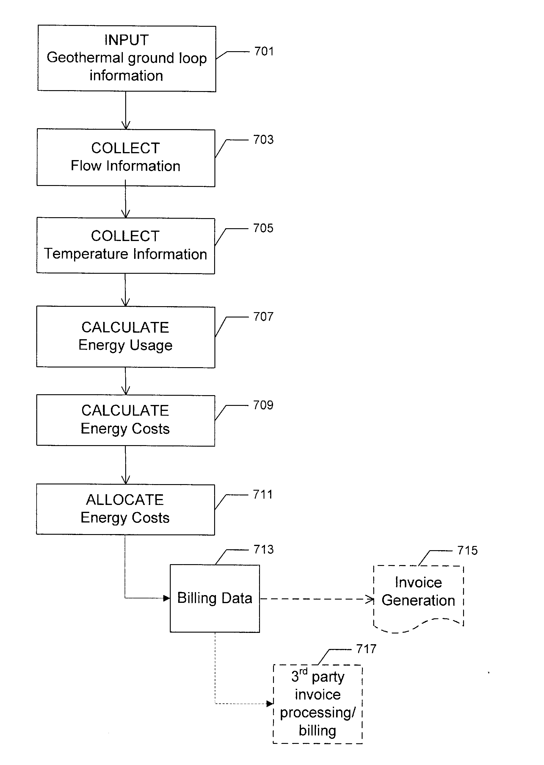
Measuring only heat output does not allow for accurate measurement of each energy input, such as electricity from the local utility and thermal energy from the ground loop and thus cannot be used to effectively allocate costs.
There was no flexibility for growth or change to the system over time nor dynamic adjustment of the pumping source to changing load patterns, leading to inefficiencies since no means are provided to vary the pumping rate depending on load.
These limitations reduce efficiency through improper pumping pressures and lead to a loss of accuracy, particularly over time as actual conditions drift from initial system weighting calculations.
Low accuracy prevents such systems from being reliably used in situations where accuracy is important, such as allocation of costs to individual loads, as may be found in multi-unit residential and commercial buildings.
Both of these requirements add significantly to system installation costs and impose additional costly requirements on each thermal load serviced by the system.
Despite improvements, a further disadvantage arising from prolonged usage of the earth-source heat-pump systems still remained: stressing of the earth's ability to transfer and / or store large quantities of thermal energy in the vicinity of the heat exchanger for extended periods of time.
A similar situation could also be seen in climates imbalanced in their annual heating or cooling needs, such as northern climates requiring substantially more heating than cooling over the course of a year or southern climates requiring the opposite.
Unfortunately, such integrated systems generally failed to realize optimum operational efficiencies.
Further, the integrated refrigerant and liquid subsystems produced a system with substantially increased complexity and maintenance requirements.
That system, however, did not employ the additional fan coil as an alternative energy source.
Again, that system did not realize optimum operational efficiencies because it did not coordinate concurrent utilization of both energy sources.
Although the system could transfer heat between any two of the heat exchangers, the Blackshaw et al. system did not utilize the third heat exchanger to augment the performance of the subterranean heat exchange loop and optimum efficiencies were not fully realized.
Although the system may boost efficiency in certain environmental conditions, it was still limited to an efficiency that essentially averaged the contribution of each source depending on existent ambient conditions.
Finally, Johnson and Tinkler in U.S. Pat. No. 6,694,766 showed a means of capturing waste heat or excess cooling capacity from an existing process but again did nothing to capture the benefit of additional heat source or sink gains that could be available through supplemental thermal systems.

Method used


Image

  • Modular Geothermal Measurement System
  • Modular Geothermal Measurement System
  • Modular Geothermal Measurement System

Examples


Embodiment Construction

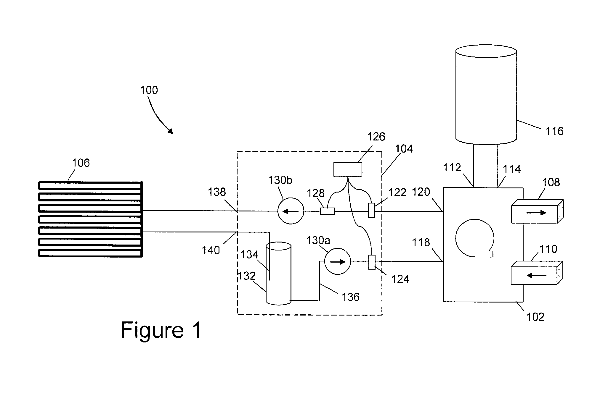
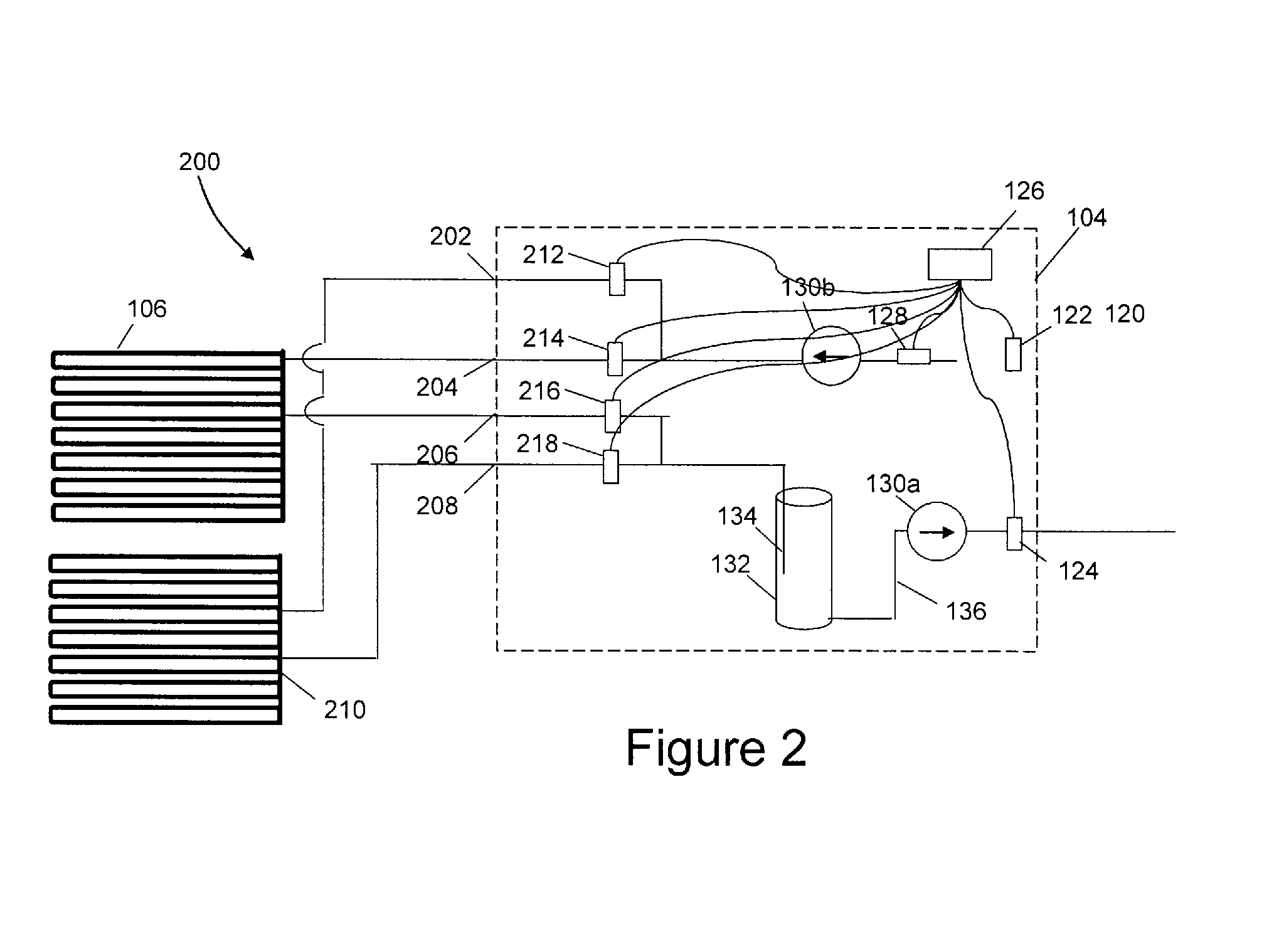
[0041]The problems encountered in the related art are overcome by the present invention which provides a modular pumping and measurement system. The pumping mechanism can be used to circulate heat transfer fluid for example, but not limited to, a geothermal heat exchanger with the fluid circulating under ground through horizontal or vertical bore loops or any of a variety of fluid reservoirs designed to exchange heat with the ground or store heat energy.

[0042]In one embodiment of the present invention, the system is part of a closed pressurized circuit, but other embodiments may include an open system (such as, but not limited to using an aquifer as the fluid source and drain) and an ambient pressure system which has advantages in certain situations, such as where anti-freeze fluid may need to be introduced in the loop after initial commissioning.

[0043]The system also allows for the combination of energy sources, a result which can provide significant improvements in system efficien...


PUM


Abstract

A modular geothermal measurement system that provides for the pumping of a heat transfer fluid. The modular unit simplifies on-site installation time by reducing the number of distinct components to be installed and allows for the optional incorporating of additional heat sources or sinks, whereby the length of ground loop can be reduced, further reducing installation costs. The modular measurement system further allows for the growth of the system over time by adding modules, increasing the ground loop pumping power while providing energy transfer data specific to each thermal load. A controller having an energy control module provides energy control points. Such a system allows the beneficiary of a geothermal investment to be billed for their benefit, enabling the investor to capture the economic benefit of the investment.

Description

[0001]This application claims priority to U.S. Patent Application Serial No. 61 / 156,646 filed Mar. 2, 2009 entitled “Modular Geothermal Measurement System” by Eric Henry Baller of Webster, N.Y., U.S.A.BACKGROUND OF THE INVENTION[0002]1. Field of the Invention[0003]This application relates generally to heating and cooling apparatus, and more particularly to a heating and cooling system having a heat transfer mechanism.[0004]2. Description of Related Art[0005]With the steadily increasing costs of fossil and other depletable types of fuels, which are presently being used to obtain desirable temperature levels in environmental and process loads, greater emphasis is being directed toward developing systems and methods to extract energy from the vast, virtually unlimited thermal energy stored in the earth and transferring that energy to loads for heating purposes and, reversely, extracting thermal energy from the loads and transferring that energy to the earth for dissipation therein for ...

Claims


Application Information

Patent Timeline
IPC IPC(8): G06Q40/00F24J3/08G05D23/19G06F1/26
CPCF24D19/1048F24D2200/11F24J3/081Y02E10/12G06Q30/04G06Q50/06Y02B10/40F24J2200/04F24T10/10F24S2201/00F24T2201/00Y02E10/10F24H15/148
Inventor BALLER, ERIC HENRY
Owner DANDELION ENERGY INC
Learn More