Multi-chip cup semi-conductor lamp

Inactive Publication Date: 2010-09-09
LEE HAN MING
View PDF18 Cites 3 Cited by
  • Summary
  • Abstract
  • Description
  • Claims
  • Application Information

AI Technical Summary

Benefits of technology

[0004]Another purpose of the present invention is to provide a multi-chip cup semi-conductor lamp, wherein the insulator

Problems solved by technology

However, the high heat effect of the LED lights still may cause the LED ligh

Method used


Image

  • Multi-chip cup semi-conductor lamp
  • Multi-chip cup semi-conductor lamp
  • Multi-chip cup semi-conductor lamp

Examples


Example

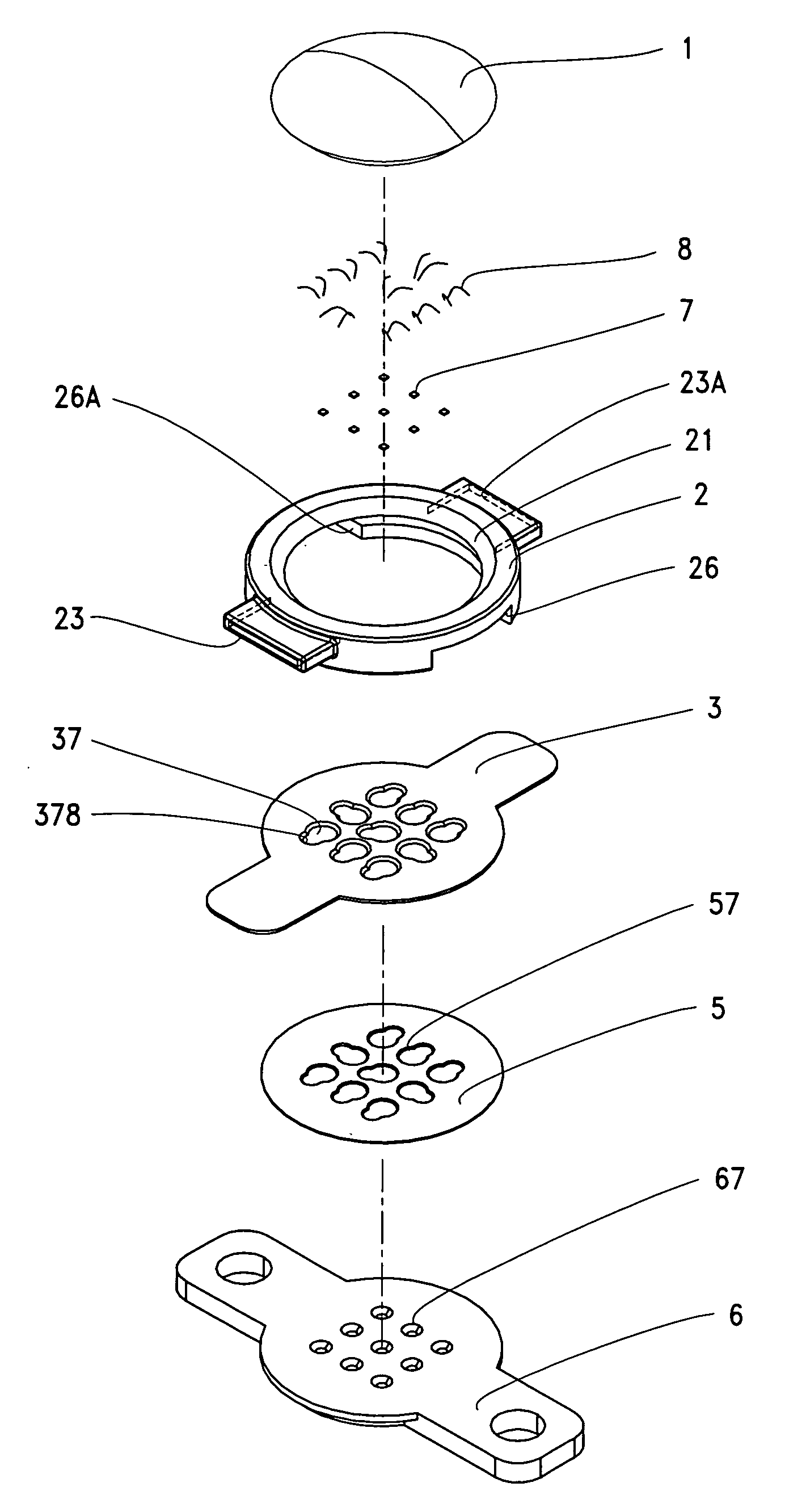
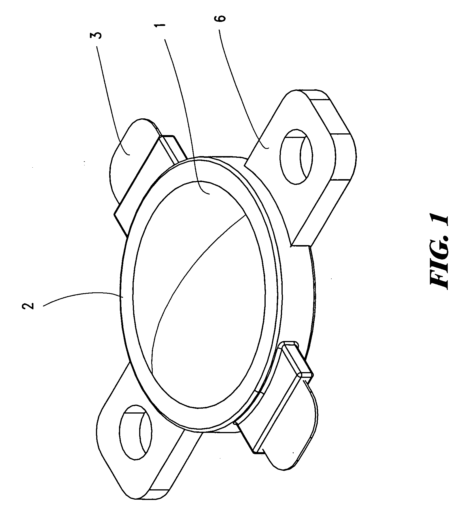
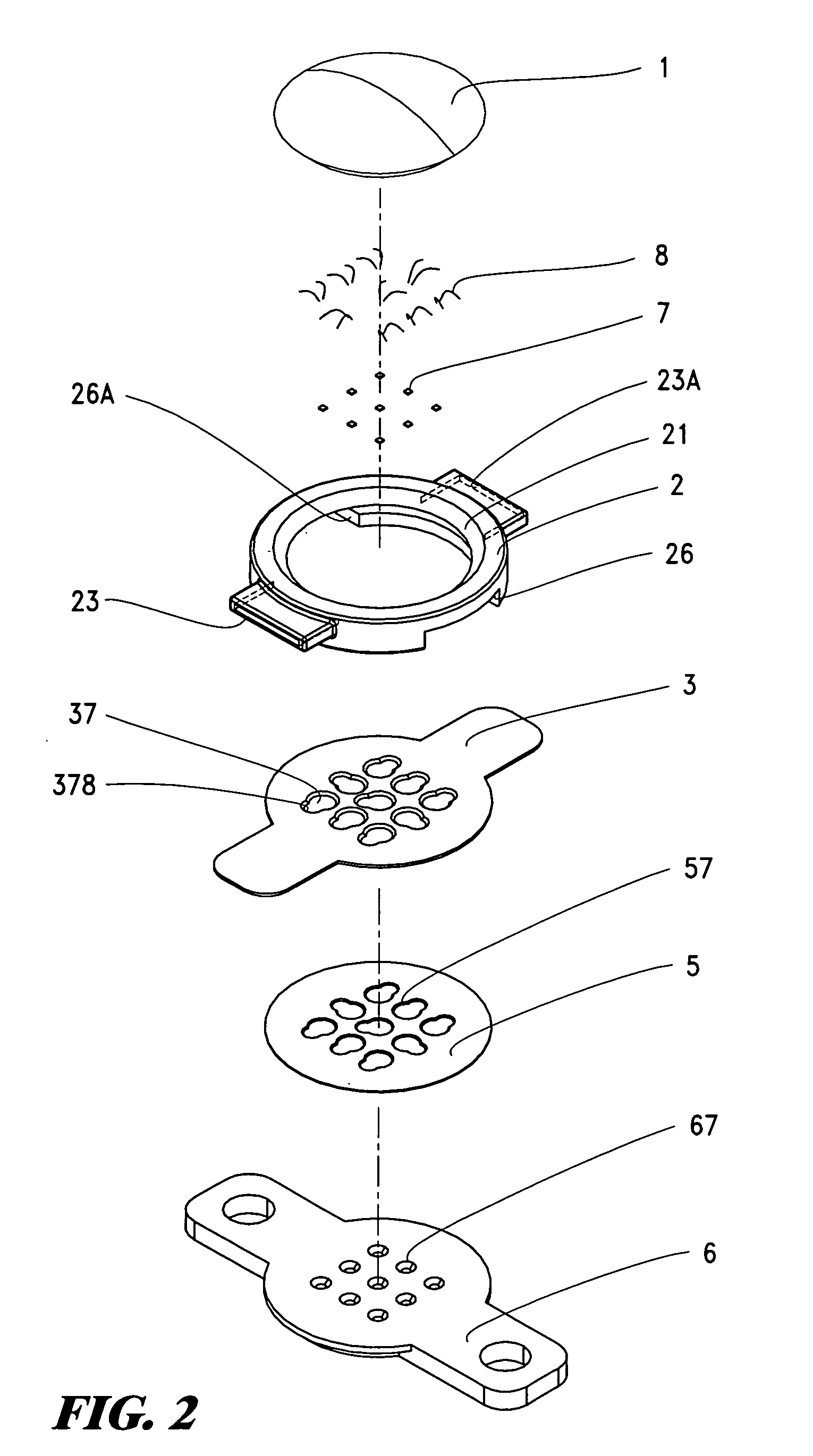
[0011]Please refer to FIG. 1 through FIG. 4, the multi-chip cup semi-conductor lamp of the present invention comprises silicon lamp cover 1, lamp housing 2, conducting plate 3, insulator 5, chip-cup lamp seat 6, chip 7, and conducting wire 8; silicon lamp cover 1 is a semi-round lamp cover made of transparent materials; lamp housing 2 is a round disk made of insulating materials with a concave ring hole 21 at the top for the installation of the outer ring below silicon lamp cover 1 and the disk is provided with concave grooves 23, 23A, 26, and 26A beneath itself; conducting plate 3 is a round plate with a plurality of taper holes 37 on the surface, the side of the taper holes are provided with semi-taper concave groove 378, the front end and the back end of the round plate surface are projected with two plates for being enclosed into the front and the back 23 and 23A of the concave groove below lamp housing 2; insulator 5 is a round piece in relative to conducting plate 3, the round...


PUM


Abstract

The present invention relates to a multi-chip cup semi-conductor lamp, comprising a silicon lamp cover, lamp housing, conducting plates, insulators, chip-cup lamp seat, chips, and conducting wires. The improvement including the chip-cut lamp seat is provided with a plurality of chip cups so that a single large power chip can be inserted as a plurality of small power chips of equal power, and the insulators, conducting plates, lamp housing, and silicon lamp cover are integrated in turn to create chip lighting sources of equally high power to achieve the effects of low temperature, low power consumption, and long service life.

Description

BACKGROUND OF THE INVENTION[0001]Thanks to the high-tech civilization, with the ever-growing urban population and limited land resources, high buildings can be built to achieve greater utilization space. However, the floors of the buildings still rely on traditional fluorescent lights or light bulbs as the light source. According to the structure of the lamps, 2 conducting pin bridged Tungsten wires are provided in the traditional glass light housing and then connected to current so that the Tungsten wires give off light and heat. In recent years, with the advancement of the electronic industry, the lamps have been gradually replaced by LED lights. However, the high heat effect of the LED lights still may cause the LED lights to decay too early, therefore reducing the service life of the LED lights. Hence, it is indeed necessary to improve the structure of the LED light to perfect it.SUMMARY OF THE INVENTION[0002]The primary purpose of the present invention is to provide a multi-chi...

Claims


Application Information

Patent Timeline
IPC IPC(8): H01J7/44
CPCF21K9/00
Inventor LEE, HAN-MING
Owner LEE HAN MING
Why Eureka
Try Eureka