
A tooth yoke separation stator structure suitable for axial flux permanent magnet motor

A technology of stator structure and permanent magnet motor, applied in the direction of magnetic circuit shape/style/structure, magnetic circuit, electromechanical device, etc., can solve the problem of increasing the application cost of axial flux permanent magnet motor and limiting axial flux permanent magnet motor Problems such as popularization and application and high cost of processing methods can achieve the effect of reducing noise and vibration, simple forming and high forming precision

Inactive Publication Date: 2019-01-11
HUAZHONG UNIV OF SCI & TECH
View PDF7 Cites 3 Cited by
  • Summary
  • Abstract
  • Description
  • Claims
  • Application Information

AI Technical Summary

Problems solved by technology

[0004] In the prior art, the stator of the axial flux permanent magnet motor is generally wound from silicon steel sheet, which is usually processed by the manufacturing method of punching and winding, although this processing method can realize the stator to a certain extent processing, but the cost of the above-mentioned processing method is relatively high, the process is more complicated, and the accuracy is difficult to guarantee, which increases the application cost of the axial flux permanent magnet motor and limits the popularization and application of the axial flux permanent magnet motor; therefore, reducing The cost of the flux permanent magnet motor stator and the simplification of the manufacturing process of the flux permanent magnet motor stator are very important to promote the development and application of the axial flux permanent magnet motor

Method used


Image

  • A tooth yoke separation stator structure suitable for axial flux permanent magnet motor
  • A tooth yoke separation stator structure suitable for axial flux permanent magnet motor
  • A tooth yoke separation stator structure suitable for axial flux permanent magnet motor

Examples


Embodiment Construction

[0028] In order to make the object, technical solution and advantages of the present invention clearer, the present invention will be further described in detail below in conjunction with the accompanying drawings and embodiments. It should be understood that the specific embodiments described here are only used to explain the present invention, not to limit the present invention.

[0029] In addition, the technical features involved in the various embodiments of the present invention described below can be combined with each other as long as they do not constitute a conflict with each other.

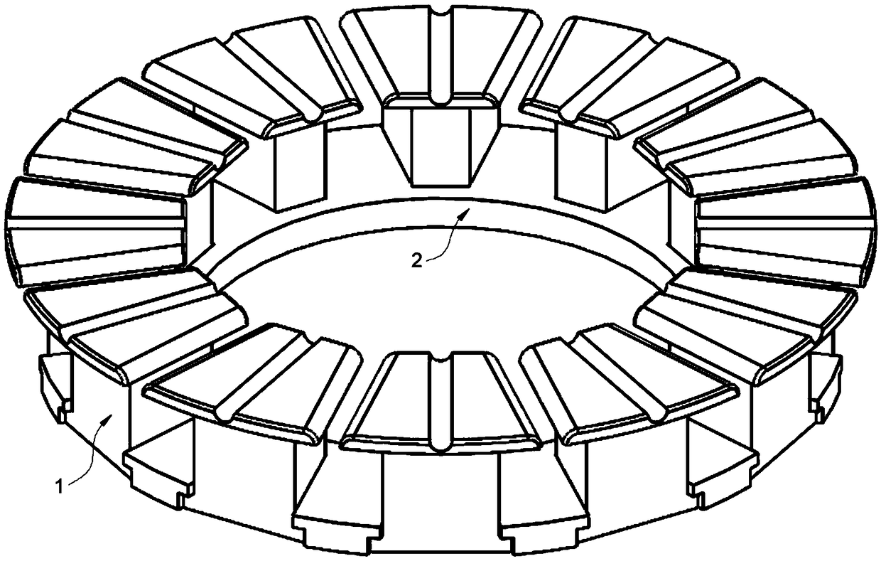
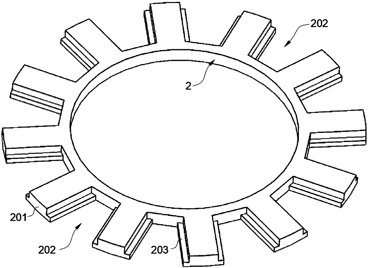
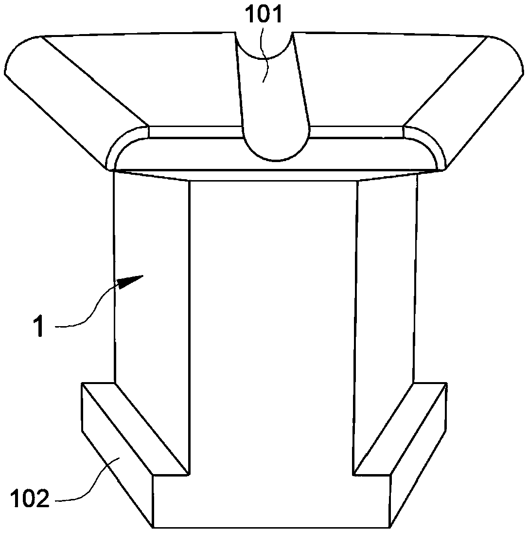
[0030] In the preferred embodiment of the present invention, the stator structure applicable to the separation of teeth and yokes of axial flux permanent magnet motors is as follows: figure 1 shown in , which consists of figure 2 The stator yoke shown in 2 and multiple as image 3 The stator tooth part 1 shown in is assembled correspondingly, and the assembly of the stator is simple ...


PUM

PropertyMeasurementUnit
Angleaaaaaaaaaa

Abstract

The invention discloses a tooth yoke separation stator structure suitable for axial flux permanent magnet motor and belongs to the field of axial magnetic flux permanent magnetic motor. A stator yokeportion having a gear shape and a stator tooth portion having a wedge structure are preferably arranged, and a plurality of stator tooth portions are assembled correspondingly and fixed on the statoryoke portion, thereby forming a stator structure suitable for an axial flux permanent magnet motor. The tooth yoke separating stator structure of the invention is suitable for axial flux permanent magnet motor, the stator tooth part and the stator yoke part are formed simply, high precision and efficiency. The invention can effectively simplify the molding process of the existing stator structure,improve the molding precision of the stator structure, and the assembling of the stator tooth part and the stator yoke part is convenient, which can greatly improve the molding efficiency of the stator structure, reduce the processing cost of the stator structure of the axial flux permanent magnet motor, promote the application of the axial flux permanent magnet motor, and has good popularizationand application value.

Description

technical field [0001] The invention belongs to the field of axial flux permanent magnet motors, and in particular relates to a tooth yoke separated stator structure suitable for axial flux permanent magnet motors. Background technique [0002] With the continuous development of economy and society and the increasing energy consumption, it has become the consensus of the whole world to replace electric excitation with permanent magnet excitation to save energy consumption, thus promoting the rapid development of permanent magnet motors. [0003] As a typical permanent magnet motor, the axial flux permanent magnet motor has an air-gap magnetic field distributed in the axial direction, and the stator and rotor are usually disc structures, which often have a larger radius, a smaller axial length, and a higher It has the characteristics of high power density, compact structure and small electromechanical time constant, and it is convenient to design a multi-disc structure, which...

Claims


Application Information

Patent Timeline
IPC IPC(8): H02K1/12H02K1/14
CPCH02K1/12H02K1/146
Inventor 李健王洪亮
Owner HUAZHONG UNIV OF SCI & TECH
Learn More