LED drive circuit, LED lamp, LED lighting appliance, and LED lighting system

a technology of led lamps and drive circuits, applied in the direction of electric variable regulation, process and machine control, instruments, etc., can solve the problems of preventing normal light control, failure of normal light control as described above, flickering and blinking , to achieve the effect of preventing failure of normal light control

Active Publication Date: 2010-09-09
SHARP KK
View PDF10 Cites 87 Cited by
  • Summary
  • Abstract
  • Description
  • Claims
  • Application Information

AI Technical Summary

Benefits of technology

[0018]An object of the present invention is to provide LED drive circuits that prevent the flickering and blinking of an LED that may occur when an LED is used with phase-control light controllers, and to provide LED lamps, LED lighting appliances, and LED lighting systems employing such LED drive circuits.

Problems solved by technology

It is however known that, with incandescent lamps of lower wattages, flickering and blinking prevent normal light control.
Due to differences in lighting characteristics between incandescent lamps and LEDs, failure of normal light control as described above is more likely to occur in LED lighting systems than in incandescent lamp lighting systems.

Method used


Image

  • LED drive circuit, LED lamp, LED lighting appliance, and LED lighting system
  • LED drive circuit, LED lamp, LED lighting appliance, and LED lighting system
  • LED drive circuit, LED lamp, LED lighting appliance, and LED lighting system

Examples


embodiment 1

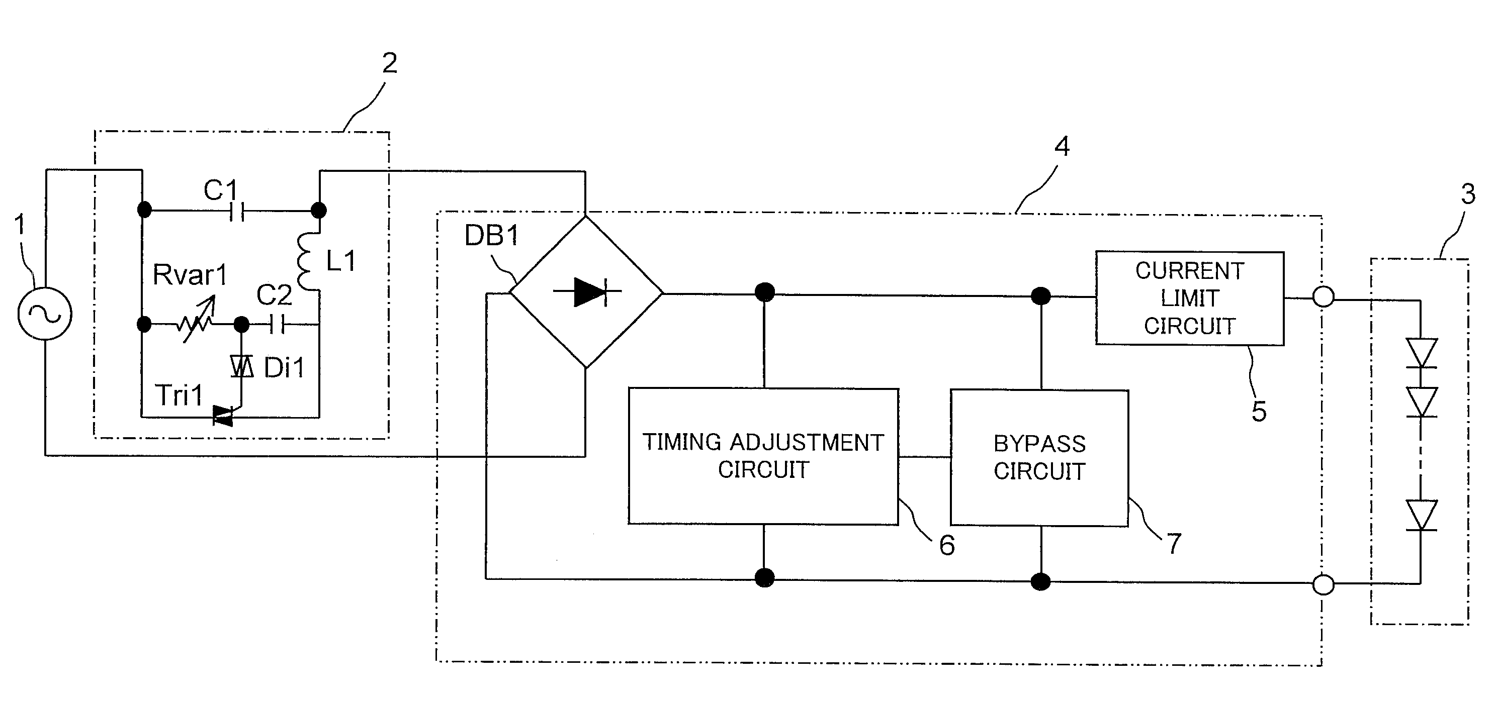
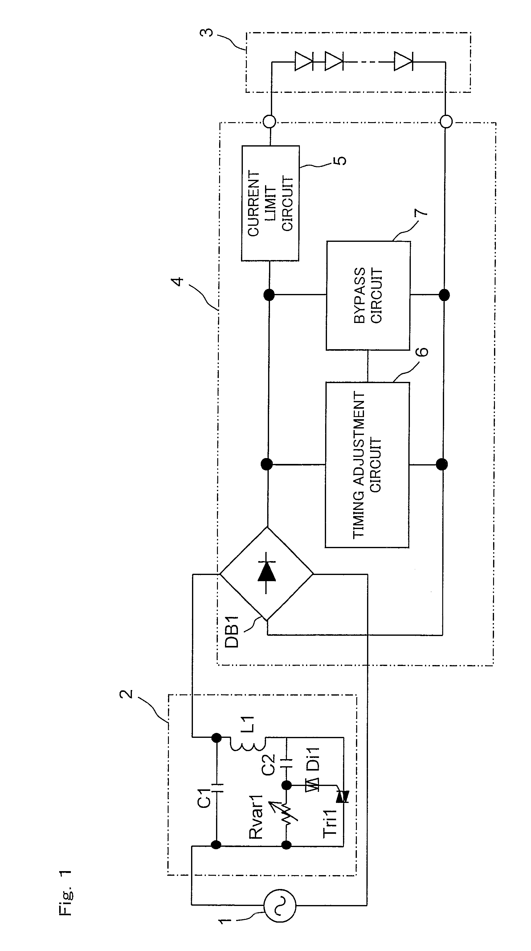
[0072]An example of the configuration of an LED lighting system according to the invention is shown in FIG. 1. In FIG. 1, such parts as find their counterparts in FIG. 14 are identified by common reference signs, and no detailed description of such parts will be repeated. The LED lighting system according to the invention shown in FIG. 1 is provided with a phase-control light controller 2, an LED module 3, and an LED drive circuit 4. The LED drive circuit 4 is an example of an LED drive circuit according to the invention, and includes a diode bridge DB1, a current limit circuit 5, a timing adjustment circuit 6, and a bypass circuit 7. In the LED lighting system according to the invention shown in FIG. 1, an AC power source 1, the phase-control light controller 2, the diode bridge DB1, the current limit circuit 5, and the LED module 3, which comprises one or more LEDs, are connected in series, and the timing adjustment circuit 6 and the bypass circuit 7 are provided between the diode...

embodiment 2

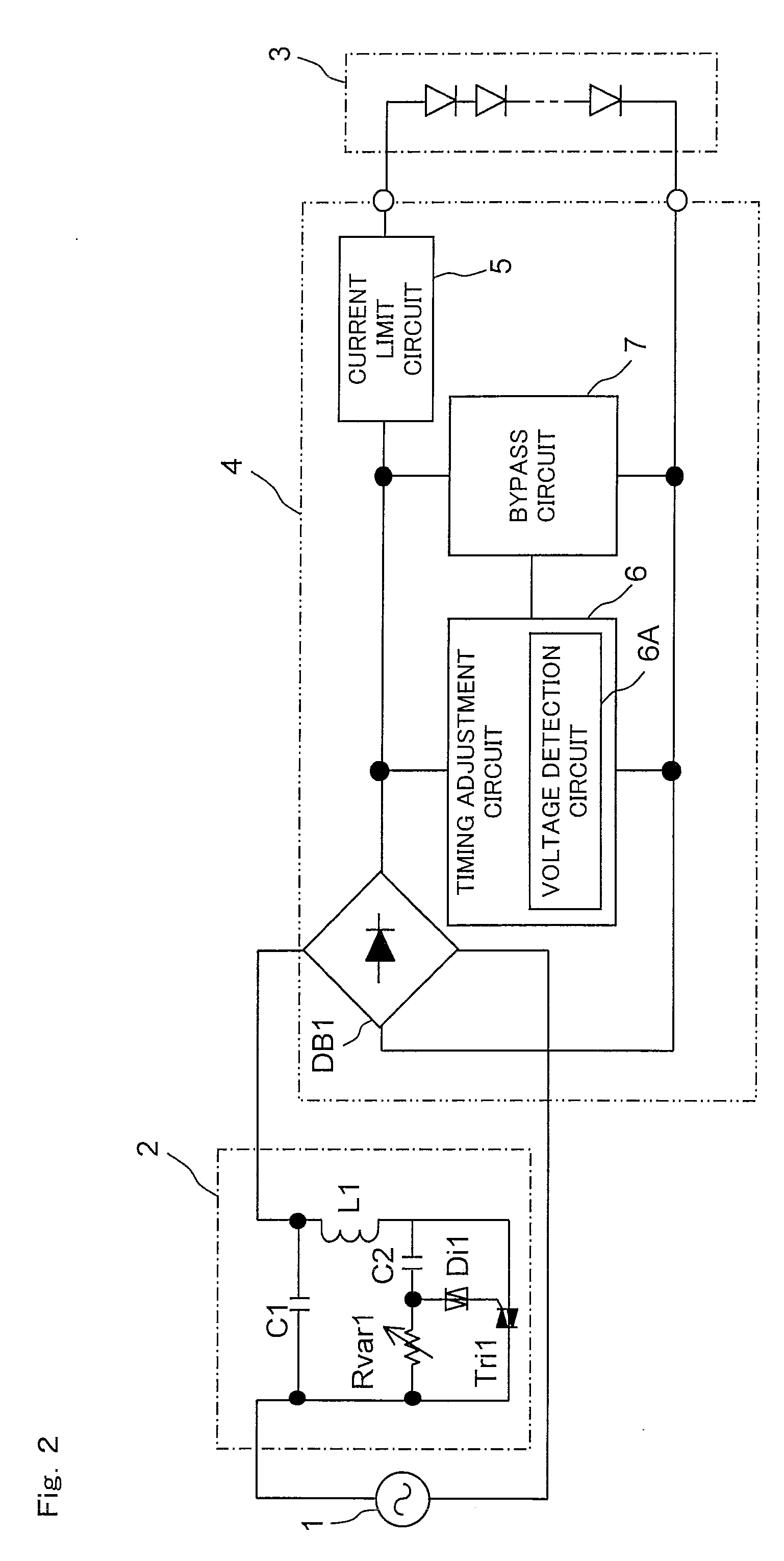
[0078]Next, an embodiment of the LED lighting system shown in FIG. 1 is shown in FIG. 2. In the configuration shown in FIG. 2, the timing adjustment circuit 6 includes a voltage detection circuit 6A which monitors the output voltage of the diode bridge DB1, and based on the output voltage of the diode bridge DB1 as detected by the voltage detection circuit 6A, the current extraction start timing and the current extraction duration are adjusted.

embodiment 3

[0079]Next, an example of the configuration shown in FIG. 2 is shown in FIG. 3. In FIG. 3, the AC power source 1 and the phase-control light controller 2 are omitted from illustration. Division resistors R31 and R32, a comparator COMP31, a constant-voltage source VS31, and a time setter 8 constitute an example of the timing adjustment circuit 6 (see FIG. 2), and the division resistors R31 and R32 constitute an example of the voltage detection circuit 6A (see FIG. 2).

[0080]The comparator COMP31 compares the midpoint voltage of the division resistors R31 and R32 with the constant voltage outputted from the constant-voltage source VS31.

[0081]When the midpoint voltage of the division resistors R31 and R32 is lower than the constant voltage outputted from the constant-voltage source VS31, the output signal of the comparator COMP31 turns the bypass circuit 7 on, and thus the bypass circuit 7 extracts a current from the current supply line through which the LED drive current is supplied to...


PUM


Abstract

An LED drive circuit receives an alternating-current voltage and drives an LED. The LED drive circuit has a current extractor which extracts a current from the current supply line through which an LED drive current is supplied to the LED, and a timing adjuster which adjusts the current extraction start timing and the current extraction duration in the current extractor.

Description

[0001]This nonprovisional application claims priority under 35 U.S.C. §119(a) on Patent Application No. 2009-53307 filed in Japan on Mar. 6, 2009, the entire contents of which are hereby incorporated by reference.BACKGROUND OF THE INVENTION[0002]1. Field of the Invention[0003]The present invention relates to LED drive circuits for driving an LED (light-emitting diode), and to such LED lamps, LED lighting appliances, and LED lighting systems as use an LED as light sources.[0004]2. Description of Related Art[0005]For their advantages such as low current consumption and long lifetimes, LEDs have been widening their application beyond display apparatuses into lighting equipment and the like. In many pieces of LED lighting equipment, a plurality of LEDs are used to obtain the desired luminance.[0006]Many common pieces of lighting equipment use a commercial AC (alternating-current) 100 V power source, and when consideration is given to cases such as where LED lamps are used in place of co...

Claims


Application Information

Patent Timeline
Patent Type & Authority Applications(United States)
IPC IPC(8): H05B37/02
CPCH05B33/0815Y02B20/383Y02B20/348H05B33/0824H05B45/397H05B45/44Y02B20/30
Inventor MARUYAMA, YASUHIRO
Owner SHARP KK
Why Eureka
Try Eureka