Polarizer binding structure and its stereo display device

Inactive Publication Date: 2010-09-09
CHUNGHWA PICTURE TUBES LTD
View PDF3 Cites 2 Cited by
  • Summary
  • Abstract
  • Description
  • Claims
  • Application Information

AI Technical Summary

Benefits of technology

[0006]The main objection of the present invention is to provide a polarizer binding structure and its stereo display device, which

Problems solved by technology

Also, it spends much manufacturing time.
Because the manufacturing method of the stereo display device 2 must use the vacuum assembly process, the cost of the equipment of the vacuum assembly process is increased a

Method used


Image

  • Polarizer binding structure and its stereo display device
  • Polarizer binding structure and its stereo display device
  • Polarizer binding structure and its stereo display device

Examples


embodiment

Preferred Embodiment

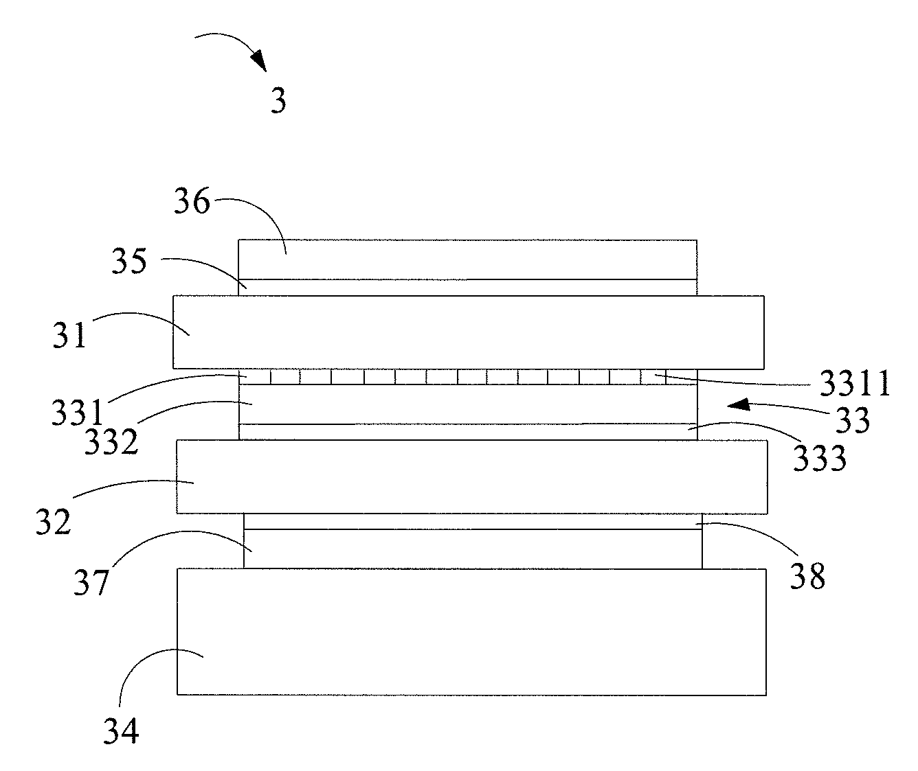
[0026]When a stereo display device of polarizer binding structure 3 is manufactured, a polarizer binding structure 33 is provided (as shown in FIG. 7). The polarizer binding structure 33 includes a polarizer 332 and an adhesive pattern layer 331. The adhesive pattern layer 331 has a plurality of gaps 3311 and the adhesive pattern layer 331 is deposed on a surface of the polarizer 332. Furthermore, an adhesive layer 333 is deposed on the other surface of the polarizer 332. The adhesive pattern layer 331 includes a plurality of vertical adhesion strips 3312 and the plurality of gaps 3311 are formed among the plurality of vertical adhesion strips 3312 (as shown in FIG. 8); or includes a plurality of transverse adhesion strips 3313 and the plurality of gaps 3311 are formed among the plurality of transverse adhesion strips 3313 (as shown in FIG. 9); or includes a plurality of oblique adhesion strips 3314 and the plurality of gaps 3311 are formed among the plurality of...


PUM


Abstract

The present invention relates to a polarizer binding structure and its stereo display device. The polarizer binding structure includes a polarizer and an adhesive pattern layer having a plurality of gaps and the adhesive pattern layer deposed on a surface of the polarizer. The stereo display device of the polarizer binding structure includes a polarizer binding structure deposed between a first liquid crystal panel and a second liquid crystal panel. The polarizer binding structure has an adhesive pattern layer, which has a plurality of gaps and a polarizer deposed on a surface of the adhesive pattern layer, wherein the adhesive pattern layer is bound to the first liquid crystal panel and the polarizer is bound to a surface of the second liquid panel. Furthermore, a backlight module deposed toward the other surface of the second liquid panel. The present invention economizes the cost of the vacuum assembly process.

Description

BACKGROUND OF THE INVENTION[0001]1. Field of the Invention[0002]The present invention relates to a polarizer structure and its stereo display device, more particular to a polarizer binding structure and its stereo display device, which is used for the area of combining a first liquid crystal panel with a second liquid crystal panel.[0003]2. Description of Related Art[0004]A manufacturing method of a stereo display device 1 of the prior art is shown in FIG. 1 to FIG. 3. First, a polarizer 10 is bound to an upper surface of a first liquid crystal panel 12 by a first adhesive layer 11. Also, a second polarizer 13 is bound to an upper surface of a second liquid crystal panel 15 by a second adhesive layer 14. Furthermore, a third polarizer 17 is bound to an under surface of the second liquid crystal panel 15 by a third adhesive layer 16 (as shown in FIG. 1). Second, a sealant 18 is bound to edges of an under surface of the first liquid crystal panel 12 and edges of the upper surface of t...

Claims


Application Information

Patent Timeline
IPC IPC(8): G02F1/1335G02B5/30
CPCG02B5/3025G02B27/2214G02F2202/28G02F1/133528G02B27/26G02B30/25G02B30/27
Inventor LIN, CHIA-LING
Owner CHUNGHWA PICTURE TUBES LTD
Why Eureka
Try Eureka