

Chemical supply system
- Summary
- Abstract
- Description
- Claims
- Application Information
AI Technical Summary
Benefits of technology
Problems solved by technology
Method used
Image

Examples
Embodiment Construction
[0018] These preferred embodiments of the present invention are now described in greater detail. Nevertheless, it should be recognized that the present invention can be practiced in a wide range of other embodiments besides those explicitly described, and the scope of the present invention is expressly not limited except as specified in the accompanying claims.
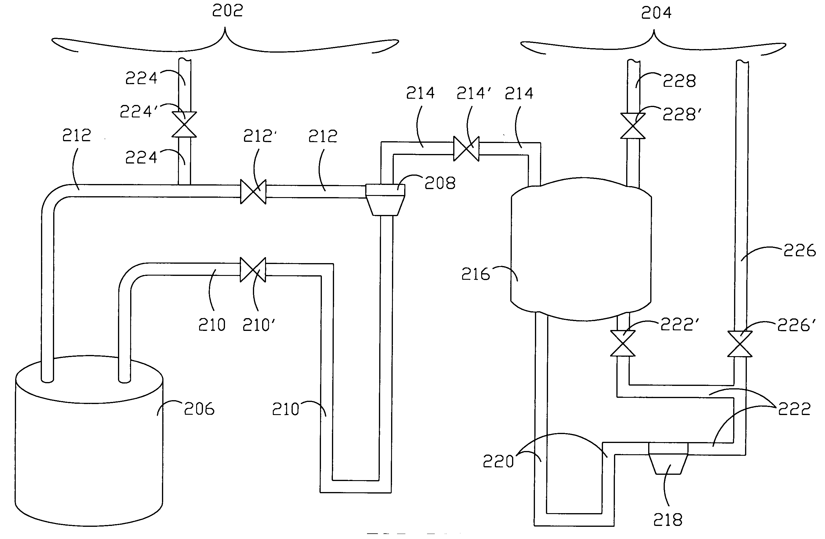
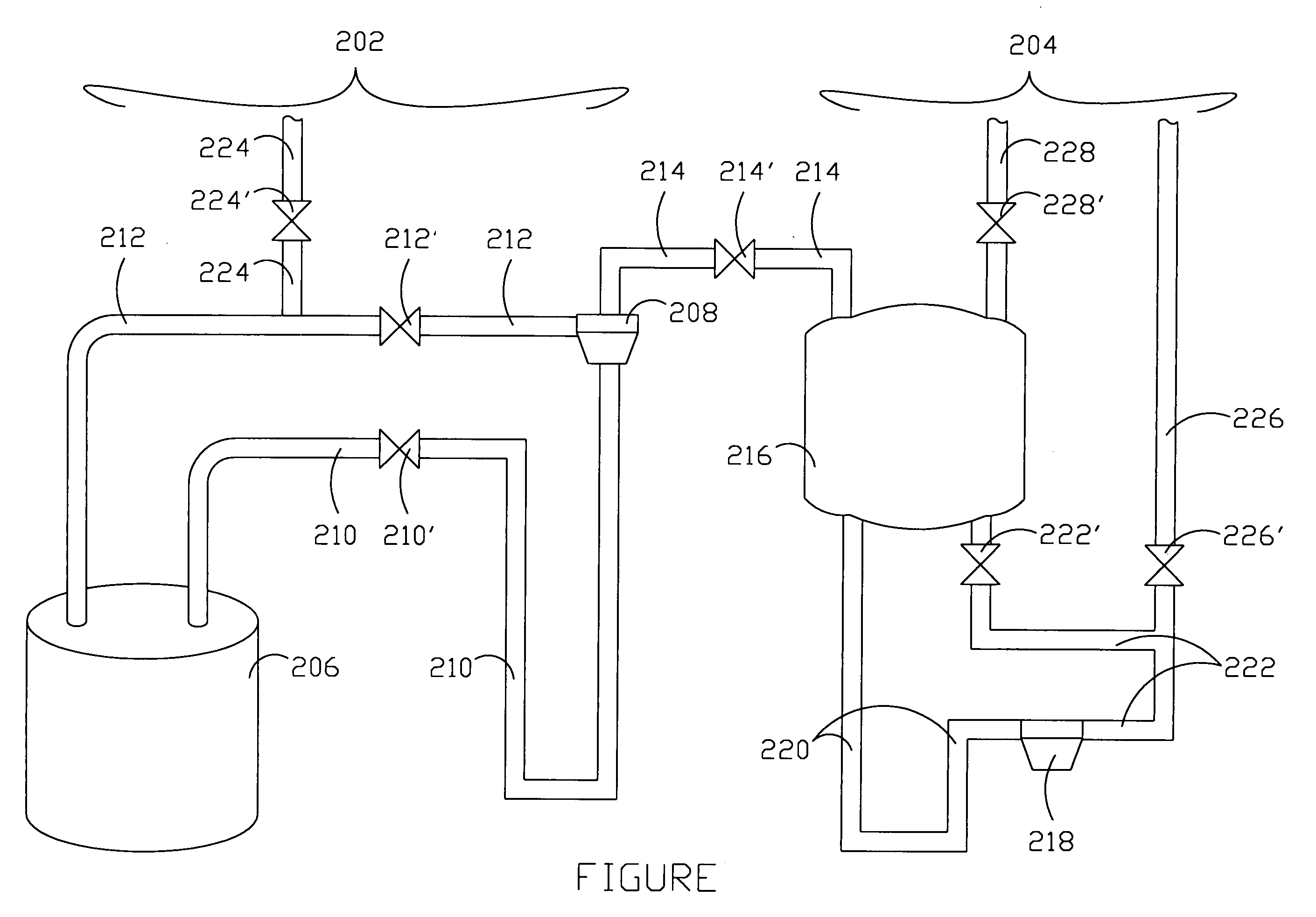
[0019] As shown in FIGURE, the embodiment of the present invention provides a chemical supply system including a first system 202 and a second system 204. The first system 202 includes a first tank 206 for storing a chemical liquid therein and a first filter 208 connecting with the first tank 206 by a first tube 210 and a second tube 212. The second system 204 includes a second tank 216 and a second filter 218. The second filter 218 connects with the second tank 216 by a fourth tube 220 and a fifth tube 222. A third tube 214 connects the first system 202 with the second system 204 for pipes the chemical liquid from the first ...
PUM
 Abstract
Description
Claims
Application Information