Optically integrated device

Inactive Publication Date: 2005-03-03
UNITED MICROELECTRONICS CORP
View PDF6 Cites 1 Cited by
  • Summary
  • Abstract
  • Description
  • Claims
  • Application Information

AI Technical Summary

Benefits of technology

[0012] According to the above description of the background of the invention, it is one objective of the present invention to provide an optically integrated device including a light condenser between a lig

Problems solved by technology

Thus the luminous efficiency of the optical integrator is limited due to the lost light L′.
Furthermore, if the design of the light sourc

Method used


Image

  • Optically integrated device
  • Optically integrated device
  • Optically integrated device

Examples


first embodiment

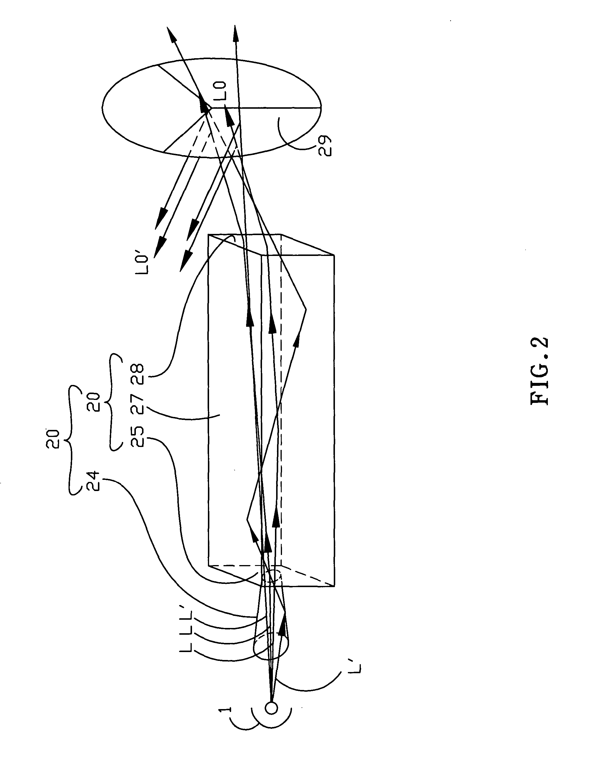
[0025] A three-dimensional perspective view of the first embodiment is showed in FIG. 2. An optically integrated device 20 includes an optical integrator 23 and an optical condenser 24. The optical integrator 23 is a pillar with four side surfaces and two end surfaces. One end surface is a light inputting face 25, and the other end surface is a light outputting face 28. A reflective part 27 distributes over the side surfaces. The light L emitted from a light source 21 is collected by the optical condenser 24 to enter the optical integrator 23 through the light inputting face 25. When the light L is emitted inside the optical integrator 23, a portion of the light L may penetrate through the optical integrator 23 directly to be filtered through a color wheel 29. The other portion of the light L that does not penetrate the optical integrator 23 directly is reflected by the reflective part 27 to penetrate the light outputting face 28, and to be filtered through the color wheel 29.

[0026]...

second embodiment

[0028] A three-dimensional perspective view of the second embodiment is showed in FIG. 3. There is an optical condenser 24 between the light source 1 and the integrator 23. The optically integrated device 20 further includes a color filter 29, which replaces the color wheel 11, attached on the light outputting face 28. An image-processing device includes a light source 1, an optically integrated device 20 and an image-forming system that includes a scrolling prism 31 and an imaging face 33. The optically integrated device 20 is set between the light source 1 and the image-forming system.

[0029] The optically integrated device 20 includes the optical integrator 23, the optical condenser 24 and the color filter 29 that includes multiple colors. The optical integrator 23 includes a light inputting face 25, a light outputting face 28 and a reflective part 27. The color filter 29 is adhered onto the light outputting face 28, wherein the color filter 29 includes a color filter 291, a color...

third embodiment

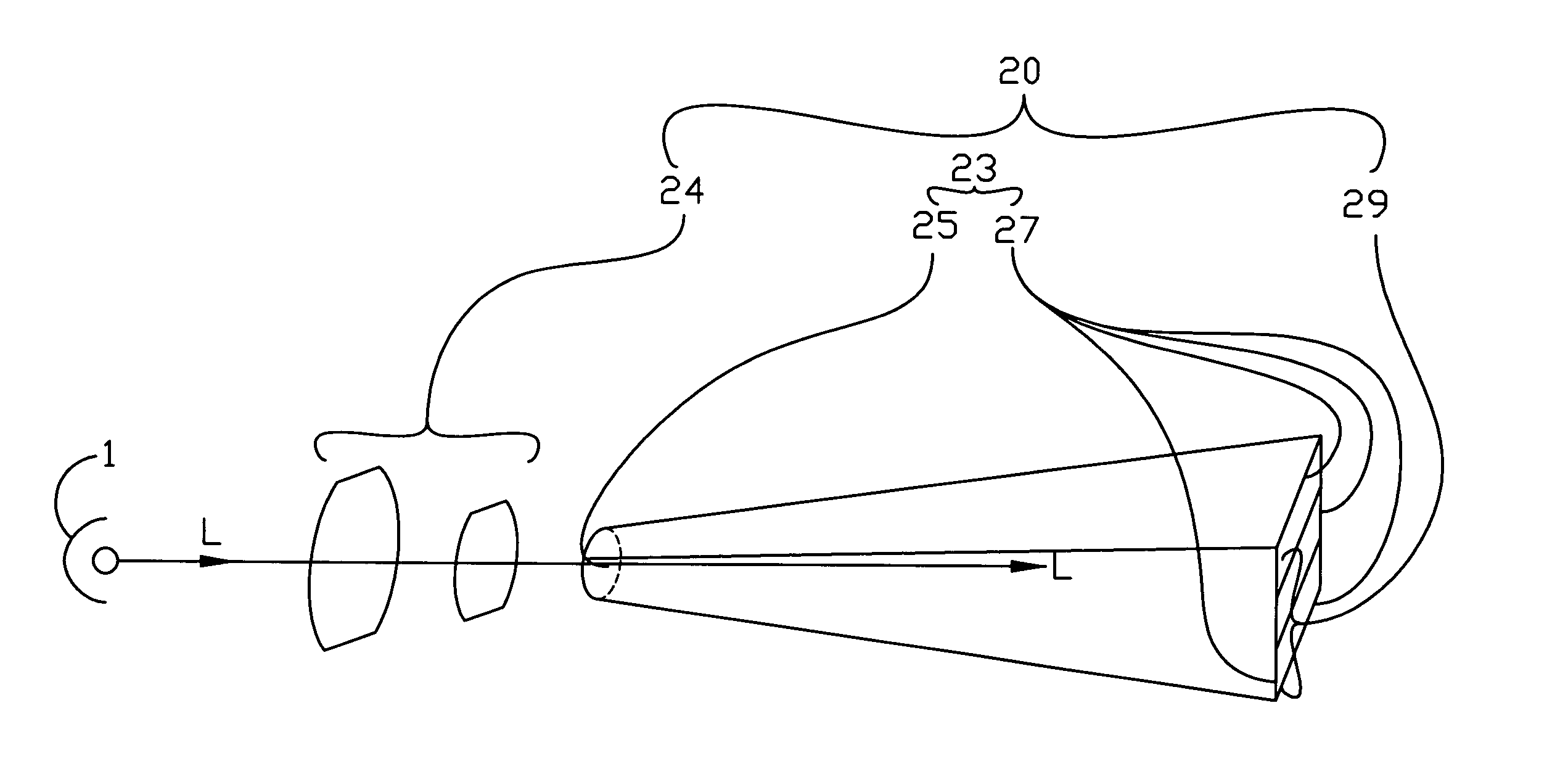
[0036] The optical integrator 23 may be the different shape as shown in FIG. 4. The optical integrator 23 of the present invention is a tapered cylinder. The shape of the optical integrator 23 may be different from all shapes of the preferred embodiments described above. The light condenser 24 that is set between the light source 1 and the optical integrator 23 may be replaced by a lens system 24 according to the different design, as shown in FIG. 4.

[0037] As shown in FIG. 4, the optical integrator 23 includes a light inputting face 25 and a reflective part 27 without a light inputting face. The optically integrated device 20 includes the optical integrator 23, that is a hollow hexahedron, and a color filter 29, that is fixed on the optical integrator 23. The color filter 29 may be a color selective panel, a spectroscope, or another device could filter through the color of the light.

[0038] The optically integrated device including a light condenser of the present invention collects...


PUM


Abstract

The present invention relates to an optically integrated device, and more particularly, to an optically integrated device with low light loss. The optically integrated device includes an optical condenser to condense the light before the light enters an optical integrator. A color filter is attached on the optical integrator to filter through a portion of the light, and reflect the other portion of the light into the optical integrator. The optically integrated device recycles the reflected light inside the optical integrator to prevent the light loss.

Description

CROSS REFERENCE TO RELATED APPLICATION [0001] This invention is related to co-pending U.S. Patent application entitled “OPTICALLY INTEGRATED DEVICE” assigned to the same assignee as the present application and incorporated herein by reference in its entirety. BACKGROUND OF THE INVENTION [0002] 1. Field of the Invention [0003] The present invention relates to an optically integrated device, and more particularly, to an optically integrated device with a high luminous efficiency. [0004] 2. Description of the Prior Art [0005] The optical system is improved as fast as the science develops. The know how of enhancing the luminous efficiency and using low power consumption while remain at the same volume of the optical system is very important. For example, the DLP (Digital Light Processing) image-processing system has the advantages of a high luminous efficiency and a small volume. [0006] As shown in FIG. 1, the optical integrator 3 of the DLP image-processing system is a pillar with four...

Claims


Application Information

Patent Timeline
IPC IPC(8): G02B7/00G02B27/09
CPCG02B27/0994G02B26/008
Inventor CHIANG, PO-LIANGTSAI, HSIN-WEN
Owner UNITED MICROELECTRONICS CORP
Why Eureka
Try Eureka