

Combining information from parallel servo channels
a technology of parallel servo channels and information, applied in the direction of maintaining head carrier alignment, digital recording, instruments, etc., can solve the problems of additional latency and information loss
- Summary
- Abstract
- Description
- Claims
- Application Information
AI Technical Summary
Problems solved by technology
Method used
Image

Examples
third embodiment
[0030]The performance of the systems in the embodiments is the same. In the third embodiment, however, the word decoder also computes an estimate of the SDR after combining, denoted by SDRC,l, based on the statistics of the weighted metrics {tilde over (m)}1,l(1) and {tilde over (m)}1,l(2), as indicated in (4).
[0031]FIG. 5 shows graphs illustrating a set of plots of metric values generated by both of the servo channels. The upper line in each graph represents the frame-by-frame metric value generated by the servo channel based upon an incorrect hypothesis, while the lower line in each graph represents the metric value generated by the servo channel based upon the correct hypothesis. The distance between the two plot lines may be regarded as an approximation of the SDR. The smaller the separation between the two plot lines, the smaller the SDR and the greater the probability of an error by the servo channel in accurately decoding the information from the servo pattern. The graph for ...
second embodiment
[0032]FIG. 6 is a plot showing the metric values for the correct and incorrect hypothesis after being weighted and combined in accordance with the present invention. FIG. 6 illustrates the restoration of an adequate SDR during the fading event of the first channel.
[0033]FIG. 7A is a plot of the SDR of the two servo channels 302A, 302B and the combined SDR generated by the timing-based servo module 300 in accordance with the second embodiment of the present invention. The value of the combined SDR is significantly higher than the values of the SDR provided by the individual servo channels, which indicates the higher reliability of LPOS decoding obtained by the combining method. The plot of FIG. 7B illustrates the values assumed by the weights for the two channels, which are output by the weight computation module 304. During the fading event of the first channel 302A, the weight for the metric provided by the first channel is close to or at zero. The dotted line indicates a weight va...
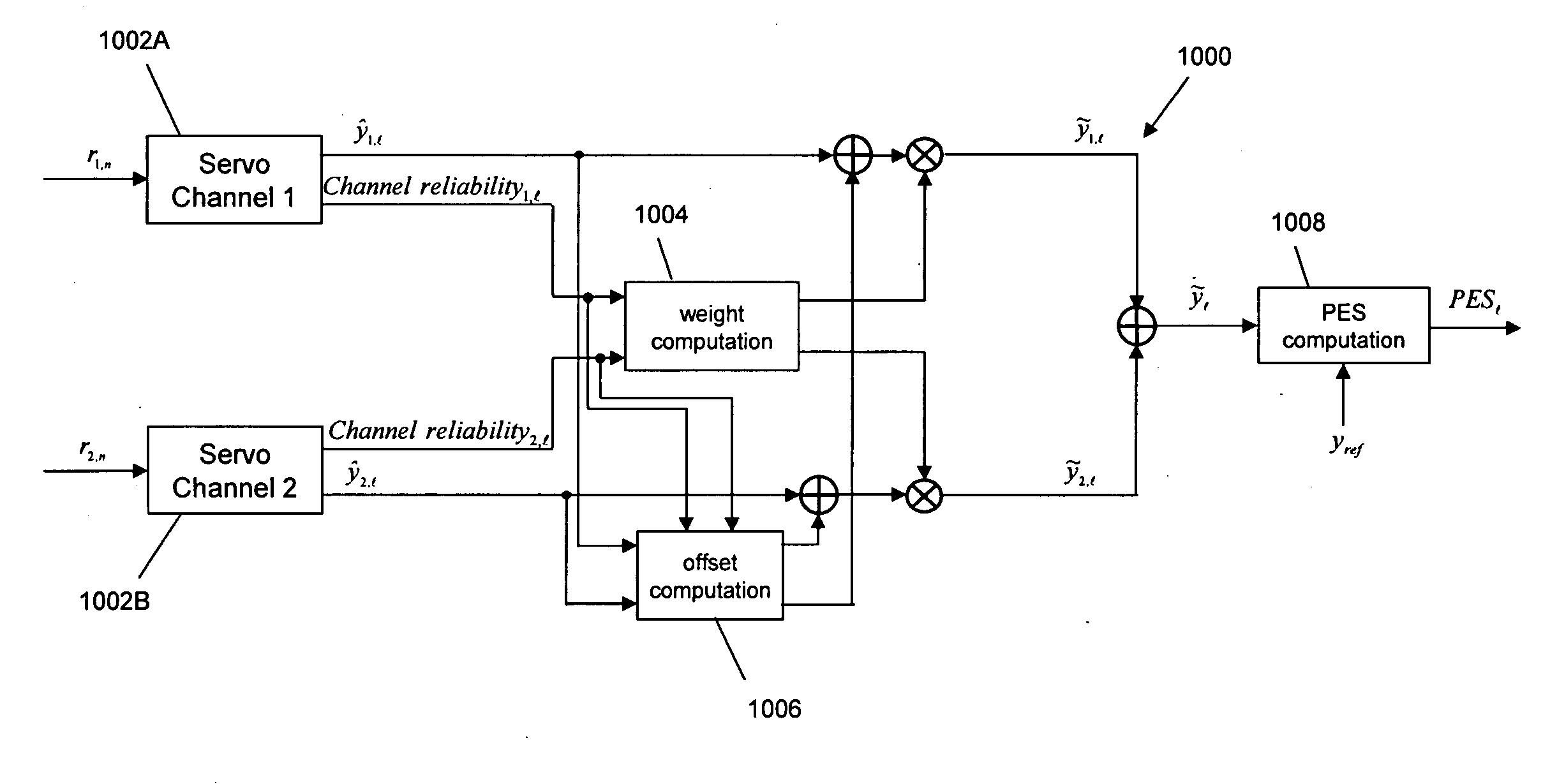
embodiment 1000
[0036]In a third aspect of the invention, the y-position estimates from the two servo channels are continuously compared. Offset terms to compensate for differences between the y-estimates from the two channels are also computed. By applying compensation of the offset terms, discontinuities in the PES sequence are avoided, which otherwise might lead to undesired effects, e.g., stop-write events in case the difference between y-estimates is of the order of a few micrometers. In the embodiment 1000 depicted in FIG. 10, after compensating for offset terms and weighting, the resulting y-estimate values {tilde over (y)}1,l and {tilde over (y)}2,l are combined to yield the combined estimate {tilde over (y)}l. The PES computation element then compares the combined estimate {tilde over (y)}l with a reference value yref to provide the position error signal PES1. The weights for combining may be obtained by considering a measure of the channel reliability of the individual servo channels, sim...
PUM
| Property | Measurement | Unit |
|---|---|---|
| weight computation | aaaaa | aaaaa |
| weight | aaaaa | aaaaa |
| velocity | aaaaa | aaaaa |
Abstract
Description
Claims
Application Information