Radio communication terminal, method for selecting communication channel and computer-readable storage medium

a radio communication terminal and computer-readable technology, applied in the field of radio communication terminals, can solve problems such as degrading throughput due to mutual interference, and achieve the effects of low-level radio-wave interference, high-speed data communication, and high quality

Active Publication Date: 2010-09-09
NEC PLATFORMS LTD
View PDF9 Cites 8 Cited by
  • Summary
  • Abstract
  • Description
  • Claims
  • Application Information

AI Technical Summary

Benefits of technology

[0007]An exemplary object of the present invention is to provide a radio communication terminal, a method for selecting a communication channel and a computer-readable storage medium which can carry out high speed data communication having high quality and low-level radio-wave interference.

Problems solved by technology

Meanwhile, as the wireless LAN is widely spread in recent years, mutual interference between the wireless LAN devices causes new problems.
That is, the mutual interference degrades throughput.

Method used


Image

  • Radio communication terminal, method for selecting communication channel and computer-readable storage medium
  • Radio communication terminal, method for selecting communication channel and computer-readable storage medium
  • Radio communication terminal, method for selecting communication channel and computer-readable storage medium

Examples


first embodiment

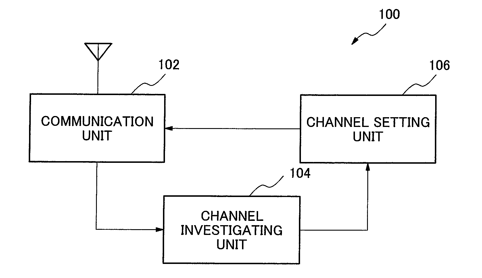
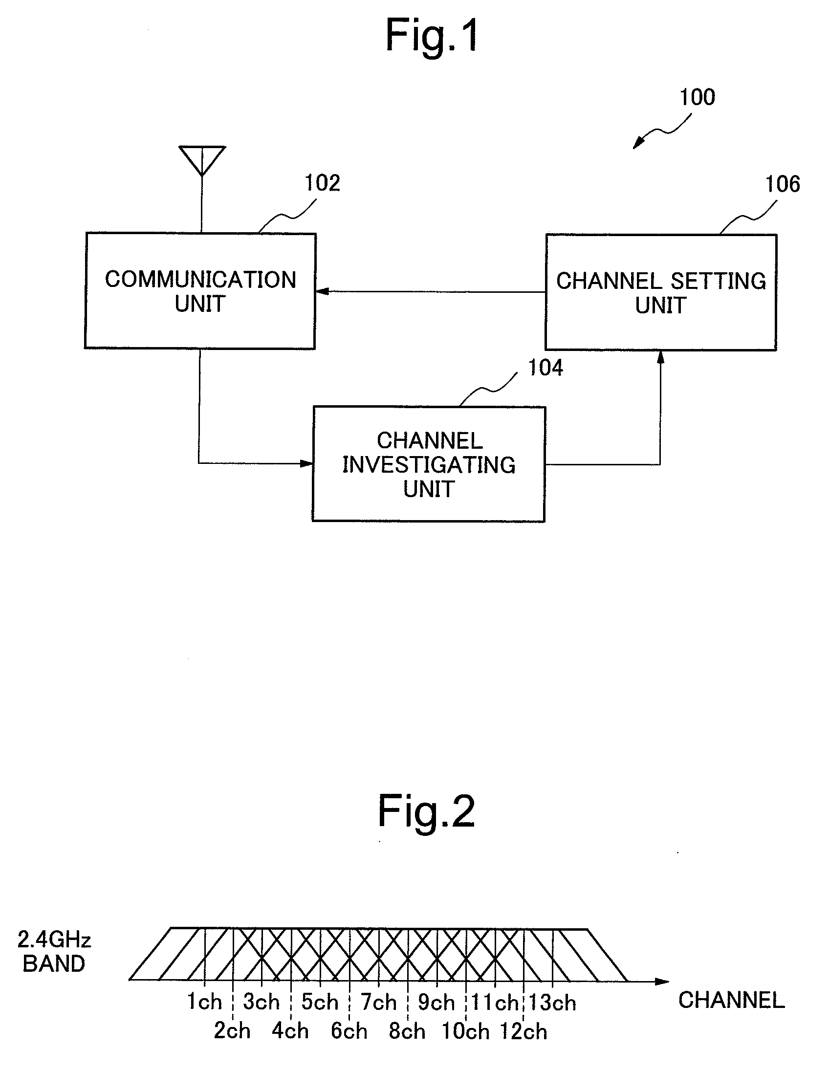
[0029]FIG. 1 is a block diagram showing a radio communication terminal 100 which is an example of a configuration of a first embodiment according to the present invention. The radio communication terminal 100 includes a communication unit 102, a channel investigating unit 104 and a channel setting unit 106. The communication unit 102 performs communication using at least one channel in a first frequency band (for example, either 2.4 GHz band or 5 GHz band).

[0030]The channel investigating unit 104 investigates all channels in the first frequency band, detects an available channel or channels in all the channels and outputs the detected result as available channel information.

[0031]On reception of the available channel information, the channel setting unit 106 determines whether or not a plurality of adjacent channels are available for communication in the first frequency band based on the available channel information. When it is determined that the plurality of adjacent channels are...

second embodiment

[0053]FIG. 6 is a block diagram showing a radio communication terminal 200 which is an example of a configuration of a second embodiment according to the present invention. The radio communication terminal 200 includes a communication unit 202, a channel investigating unit 204 and a channel setting unit 206. The communication unit 202 can perform communication by using least one channel in a second frequency band in addition to the first frequency band.

[0054]The channel investigating unit 204 investigates all channels in the first and the second frequency bands, detects an available channel in each of the first and the second frequency bands and outputs the detection result as available channel information. Further, when no available channel is detected, the channel investigating unit 204 outputs the number of at least one channel having a low noise level among the channels as the available channel information.

[0055]The channel setting unit 206 receives the available channel informa...

third embodiment

[0078]FIG. 11 is a block diagram showing a radio communication terminal 300 which is an example of a configuration of a third embodiment according to the present invention. The radio communication terminal 300 includes a CPU (Central Processing Unit) 301, a communication control unit 302, an antenna 303, a radio wave state analyzing unit 304, an operation and display unit 305, a RAM (Random Access Memory) 306 and a ROM (Read Only Memory) 307.

[0079]CPU 301 controls the whole of the radio communication terminal 300. The communication control unit 302 controls wireless communication in a first frequency band (for example, 2.4 GHz band) and a second frequency band (for example, 5 GHz band). The antenna 303 sends and receives a radio wave. The radio wave state analyzing unit 304 analyzes data obtained through channel search and a channel monitor and checks a state of a surrounding radio wave such as a noise level. The operation and display unit 305 is handled by a user and displays requi...


PUM


Abstract

A radio communication terminal includes a communication unit, a channel investigating unit and a channel setting unit. The communication unit communicates using at least one channel in a first frequency band. The channel investigating unit investigates all channels in the first frequency band, detects an available channel in the all channels and outputs a detection result as available channel information. The channel setting unit receives the available channel information, determines whether or not a plurality of channels adjacent to each other in the first frequency band are available for communication based on the available channel information.

Description

RELATED APPLICATIONS[0001]This application is based on Japanese Patent Application No. JP 2008-056947 filed on Mar. 6, 2008, and including a specification, claims, drawings and summary. The disclosure of the above Japanese Patent Application is incorporated herein by reference in its entirety.TECHNICAL FIELD[0002]The present invention relates to a radio communication terminal, a method for selecting a communication channel and a computer-readable storage medium.BACKGROUND ART[0003]In recent years, IEEE (Institute of Electrical and Electronics Engineers) 802.11n (draft version 2.0 and newer version) specification is proposed (drawn) as a standard which intends to increase capacity and communication speed of a wireless LAN (Local Area Network). IEEE802.11n realizes effective communication speed over 100 Mbps by using 2.4 GHz frequency band and 5 GHz frequency band. IEEE802.11n adopts a channel bonding technique in which a plurality of channels (bandwidth used for communication) is bon...

Claims


Application Information

Patent Timeline
Patent Type & Authority Applications(United States)
IPC IPC(8): H04W4/00
CPCH04W72/085H04W72/542
Inventor HASEGAWA, KAZUHIKO
Owner NEC PLATFORMS LTD
Why Eureka
Try Eureka