Communication system and communication device

a communication system and communication device technology, applied in the field of communication system and communication device, can solve the problems of inability to make communication for a long time, the communication device to have a wireless charging function, and the limited application range of the communication device, so as to reduce the significant consumption of power obtained from the signal that has passed through the magnetic-field antenna or prevent the effect of wasting power

Active Publication Date: 2017-06-06
MURATA MFG CO LTD
View PDF13 Cites 1 Cited by
  • Summary
  • Abstract
  • Description
  • Claims
  • Application Information

AI Technical Summary

Benefits of technology

[0008]Preferred embodiments of the present invention provide a communication system that does not require a configuration for wireless charging and enables data communication between communication devices even under a situation where an operation with a battery cannot be performed.
[0010]With the above-described structure, the first communication device is able to obtain the power from the signal that has passed through the magnetic-field antenna so as to perform the data communication. Therefore, high-speed data communication between the communication devices is able to be performed even under a situation where the first communication device cannot operate with the battery.
[0011]It is preferable that the first communication device include a switch that controls power source supply to the data processor or an operation of the main CPU, and a power supply switching unit that switches the switch to block the power source supply to the data processor or to stop the operation of the main CPU when electric power or a voltage which is supplied from the main power source is lower than a threshold value. With this structure, waste consumption of the power obtained from the signal that has passed through the magnetic-field antenna is significantly reduced or prevented.
[0015]With the above-described structure, the first communication device is able to obtain the power from the signal that has passed through the magnetic-field antenna so as to perform the data communication. Therefore, high-speed data communication between communication devices is able to be performed even under a situation where the first communication device cannot operate with the battery.
[0016]It is preferable that the first communication device further include a switch that controls a power source supply to the data processor or an operation of the main CPU, and a power supply switching unit that switches the switch to block the power source supply to the data processor or to stop the operation of the main CPU when electric power or a voltage which is supplied from the main power source is lower than a threshold value. With this structure, waste consumption of power obtained from the signal that has passed through the magnetic-field antenna is significantly reduced or prevented.
[0017]According to various preferred embodiments of the present invention, the first communication device is able to obtain the power from the signal that has passed through the magnetic-field antenna so as to perform the data communication. Therefore, high-speed data communication between communication devices is able to be performed even under a situation where the first communication device cannot operate with the battery.

Problems solved by technology

However, these communication methods require a battery of the mobile terminal to be charged before data communication when a residual quantity of the battery runs out and it cannot make communication for a long period of time during the charging.
However, the method as disclosed in Japanese Unexamined Patent Application Publication No. 2009-247125 requires a communication device to have a wireless charging function and an application range thereof is limited.
Further, there also arises a problem that data communication cannot be performed when the battery breaks down and so on and abnormality occurs in a charging operation.

Method used


Image

  • Communication system and communication device
  • Communication system and communication device
  • Communication system and communication device

Examples


Embodiment Construction

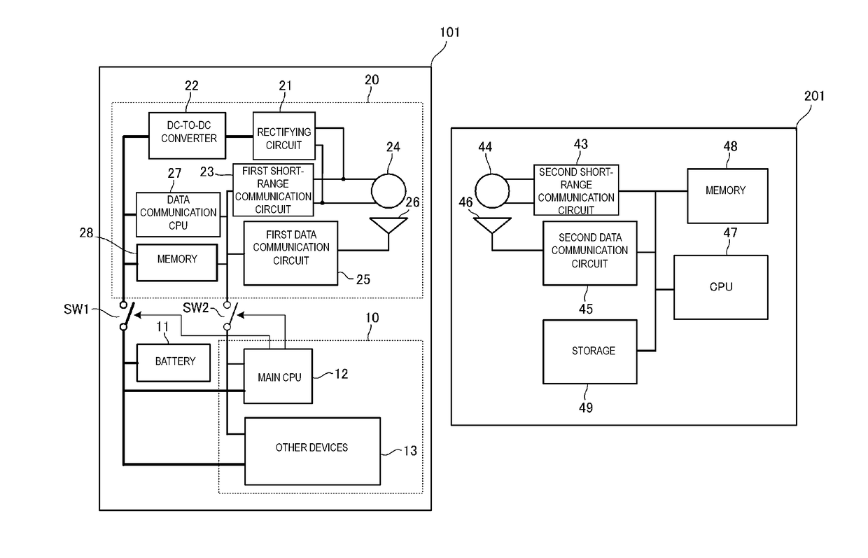
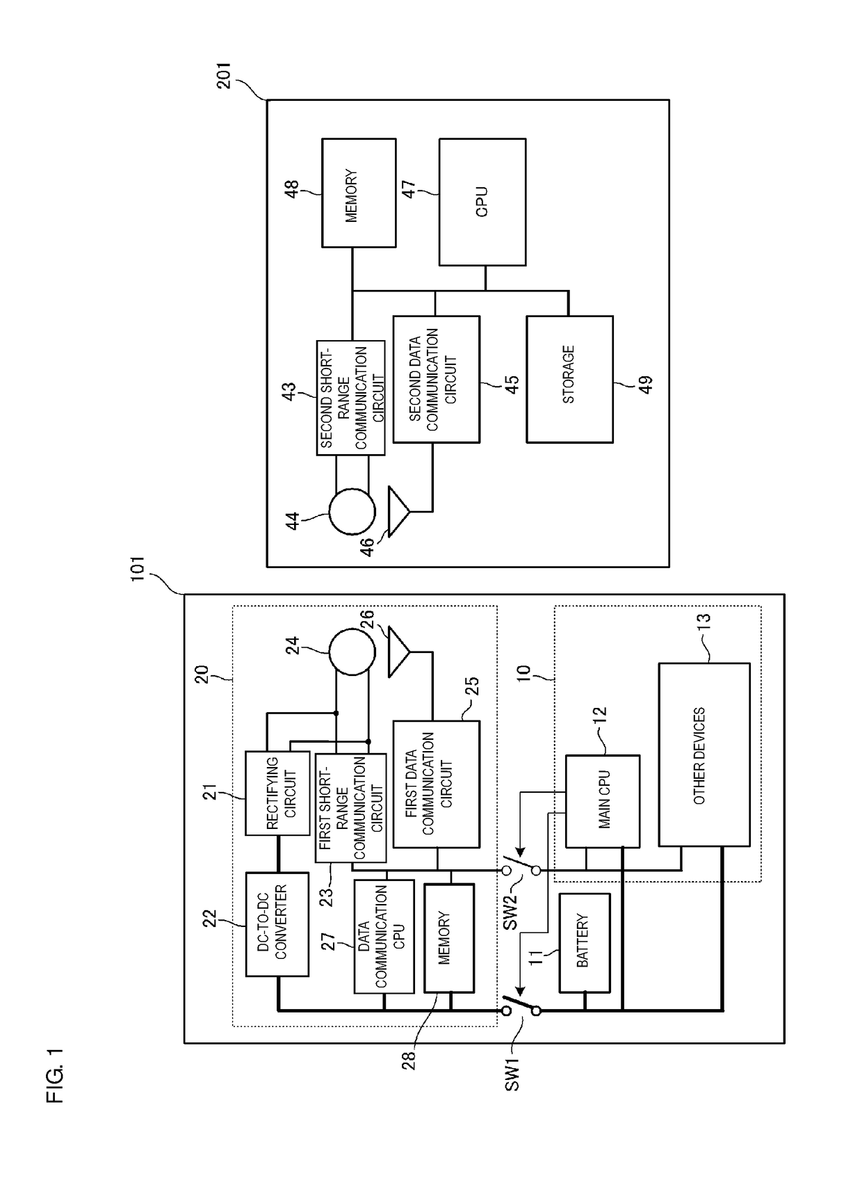
[0022]FIG. 1 is a block diagram of a communication system according to a preferred embodiment of the present invention. The communication system preferably includes a first communication device 101 and a second communication device 201. The first communication device 101 is a device that holds data of relatively large capacity in a memory or the like, and is a mobile device such as a digital camera and a cellular phone, for example. The second communication device 201 is a data storage device including such as a large-capacity storage, and is a stationary device such as a personal computer (PC). Short-range wireless communication is communication (a typical example thereof is near field communication (NFC)) using a high frequency (HF) band, for example, and high-speed data communication is communication (typical examples thereof are wireless LAN, Bluetooth (registered trademark), and TransferJet (registered trademark)) using an ultra high frequency (UHF) band or a super high frequen...


PUM


Abstract

A communication system includes a first communication device that operates using a battery as a main power source and a second communication device that communicates with the first communication device. The second communication device includes a second high-speed data communication unit including a second data communication antenna and a second short-range communication unit including a second magnetic-field antenna for short-range communication. The first communication device includes a first short-range communication unit including a first magnetic-field antenna and a first high-speed data communication unit including a first data communication antenna. When an electromotive voltage of the battery lowers, switches are turned OFF and electric power from a power conversion circuit including a rectifying circuit and a DC-to-DC converter is supplied to a communication controller.

Description

BACKGROUND OF THE INVENTION[0001]1. Field of the Invention[0002]The present invention relates to a communication system and a communication device that perform communication between two communication devices over a short range.[0003]2. Description of the Related Art[0004]When large-capacity data such as pictures and videos stored in a mobile terminal is transferred to a stationary terminal such as a personal computer (PC), a method in which the terminals communicate with each other by wire using a local area network (LAN), a universal serial bus (USB), or the like, a method in which the terminals communicate with each other using a wireless LAN, and a method in which the terminals communicate with each other by proximity high-speed wireless communication using TransferJet (registered trademark) or the like have been used generally.[0005]However, these communication methods require a battery of the mobile terminal to be charged before data communication when a residual quantity of th...

Claims


Application Information

Patent Timeline
Patent Type & Authority Patents(United States)
IPC IPC(8): H04B5/00H01Q1/24H01Q21/28H04W4/00H01Q1/22G06F1/26H02J50/00H04W4/80
CPCH04B5/0031G06F1/26H01Q1/2291H01Q1/243H01Q1/248H01Q21/28H02J50/10H04B5/0037H04B5/0075H04W4/008H02J50/00G06F1/1698G06F1/263H04W4/80
Inventor IKEDA, NAOTO
Owner MURATA MFG CO LTD
Why Eureka
Try Eureka