Variable displacement pump

Active Publication Date: 2010-09-09
HITACHI AUTOMOTIVE SYST LTD
View PDF9 Cites 59 Cited by
  • Summary
  • Abstract
  • Description
  • Claims
  • Application Information

AI Technical Summary

Benefits of technology

[0003]However, the above-mentioned conventional variable displacement pump takes such a structure that the biasing force of the spring is balanced with a hydraulic pressure force based on the internal pres

Problems solved by technology

Accordingly, it is required to increase the biasing force of the spring

Method used


Image

  • Variable displacement pump
  • Variable displacement pump
  • Variable displacement pump

Examples


Embodiment Construction

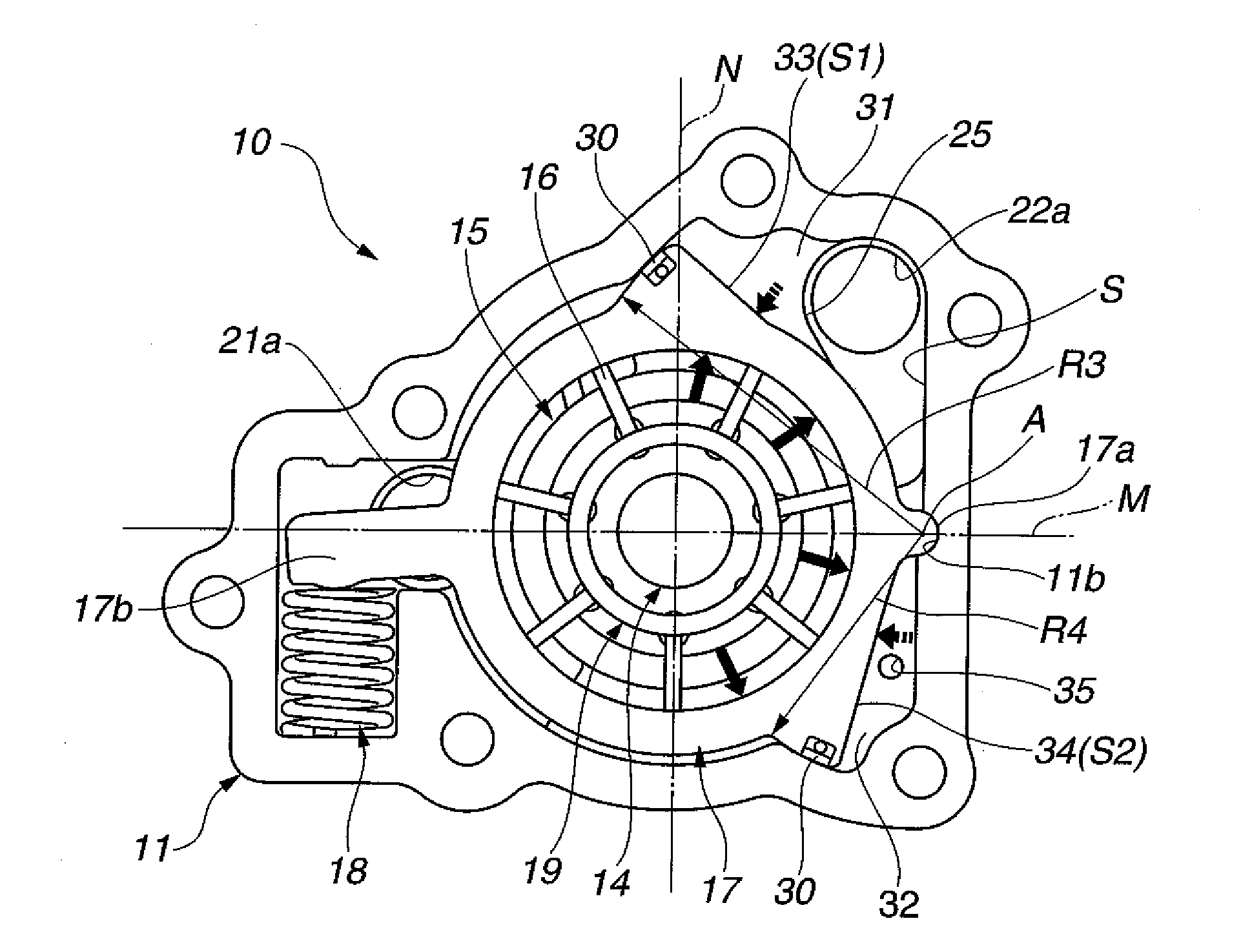
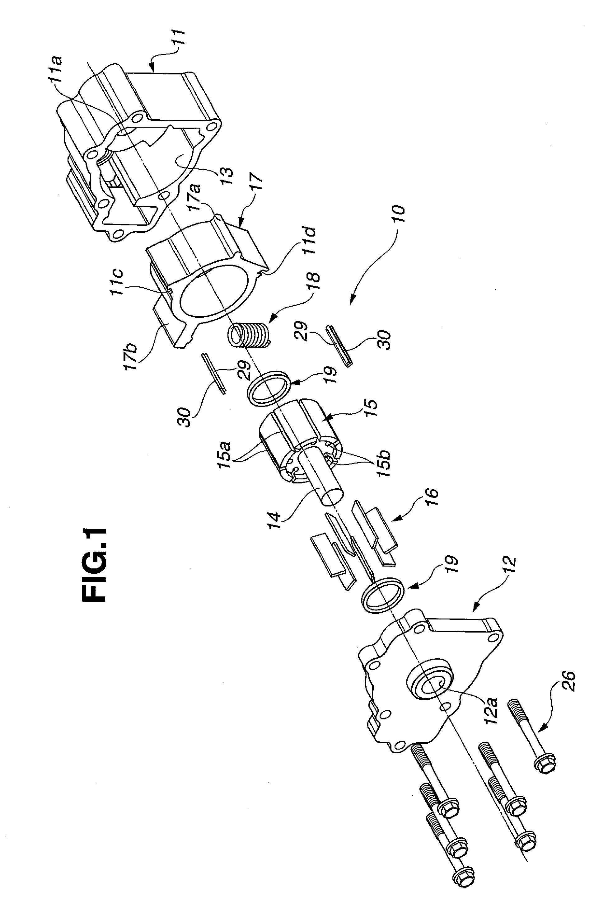
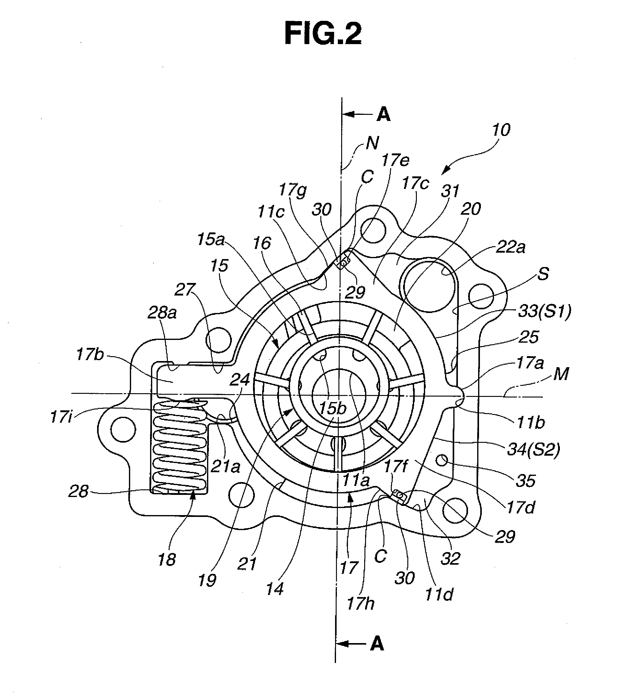
[0036]Referring now to FIGS. 1 to 9 of the drawings, a first embodiment of a variable displacement oil pump according to the present invention is illustrated by the reference numeral 10. As shown in FIGS. 1 to 3, oil pump 10 is disposed at a front end section or the like of a cylinder block of an automotive internal combustion engine and includes a housing (no numeral) which has container-shaped pump body 11 which is formed to be opened at its one end and formed thereinside with pump accommodating chamber 13 as a cylindrical space. Cover member 12 closes the opening at the one end of pump body 11. Drive shaft 14 is rotatably supported by the housing and passes through an about central portion of pump accommodating chamber 13 so as to be rotationally driven by a crankshaft of the engine. Pump element (no numeral) includes rotor 15 which is rotatably disposed inside pump accommodating chamber 13 and has a central section connected to drive shaft 14. Vanes 16 are respectively disposed ...


PUM


Abstract

A variable displacement oil pump for an automotive engine. The oil pump includes a cam ring accommodating thereinside a pump element having a rotor. The cam ring is swingingly movably accommodated in a housing and biased in a direction to increase an eccentricity amount of the cam ring relative to the axis of the rotor by a biasing member. First and second pressure chambers are defined inside the housing by the outer peripheral section of the cam ring. The first pressure chamber is supplied with a discharge pressure to be applied to the cam ring to oppose to a biasing force of the biasing member. The second pressure chamber is supplied with the discharge pressure to be applied to the cam ring to assist the biasing force of the biasing member. Additionally, a control device is provided for controlling supply of the discharge pressure to the second pressure chamber.

Description

BACKGROUND OF THE INVENTION[0001]This invention relates to a variable displacement pump which is applied, for example, to a hydraulic pressure source for supplying hydraulic oil to various sliding sections and the like of an automotive internal combustion engine, and more particularly to the variable displacement pump whose discharge amount (discharge pressure) is variable in accordance with engine operating conditions.[0002]As a conventional variable displacement pump to be used for an oil pump of an automotive vehicle, there is proposed one disclosed in International Application Publication (Tokuhyou) No. 2008-524500. In summary, this variable displacement pump is of a so-called vane type and arranged such that a discharge pressure is selectively supplied to two pressure chambers defined between a housing and a cam ring so as to control the eccentricity amount of the cam ring which is always biased in a direction to be eccentric relative to the center axis of a rotor, thereby rend...

Claims


Application Information

Patent Timeline
IPC IPC(8): F04C14/22
CPCF04C2/3442F04C14/223F04C2210/14F04C14/226
Inventor WATANABE, YASUSHIOHNISHI, HIDEAKINAGANUMA, ATSUSHI
Owner HITACHI AUTOMOTIVE SYST LTD
Why Eureka
Try Eureka