Muzzle attachment system

a technology of muzzle attachment and muzzle, which is applied in the field of muzzle attachment system, can solve the problems of preventing easy manual removal of muzzle attachment, and achieve the effects of preventing fouling, quick and easy attachment and detachment, and preventing fouling

Inactive Publication Date: 2010-09-16
YANKEE HILL MACHINE
View PDF38 Cites 36 Cited by
  • Summary
  • Abstract
  • Description
  • Claims
  • Application Information

AI Technical Summary

Benefits of technology

[0014]According to one aspect of the present invention the first and second engagement means include complementary coarse threaded engagement portions. The coarse threaded engagement portions allow for quick and easy attachment and detachment. The first engagement means and second engagement means also include an annular grooved surface having a plurality of grooves, and a grooved surface engagement mechanism.
[0015]The annular grooved surface and the grooved surface engagement mechanism engage one another with sufficient force to overcome torsional forces acting on the muzzle attachment during use, even when the muzzle attachment is not completely screwed on to the muzzle distal portion. However, the force exerted between the annular grooved surface and the grooved surface engagement mechanism still permits easy manual removal of the muzzle attachment.
[0016]According to another aspect of the present invention the first and second engagement portions include first and second position stops that prevent overtightening of the coarse threaded portions and abut to form a gas seal, the gas seal substantially preventing gases exiting the muzzle distal portion from reaching the coarse threaded portions, thereby preventing fouling.
[0017]According to a further aspect of the present invention, the muzzle distal portion is a flash suppressor, the flash suppressor including at least two elongated ports substantially equally skewed from normal relative to a firing axis of the firearm, the at least two elongated ports being substantially evenly distributed around the circumference of the flash suppressor. Thus, the flash suppression of the distal portion is enhanced when no muzzle attachment is in place.

Problems solved by technology

However, the force exerted between the annular grooved surface and the grooved surface engagement mechanism still permits easy manual removal of the muzzle attachment.

Method used


Image

  • Muzzle attachment system
  • Muzzle attachment system
  • Muzzle attachment system

Examples


Embodiment Construction

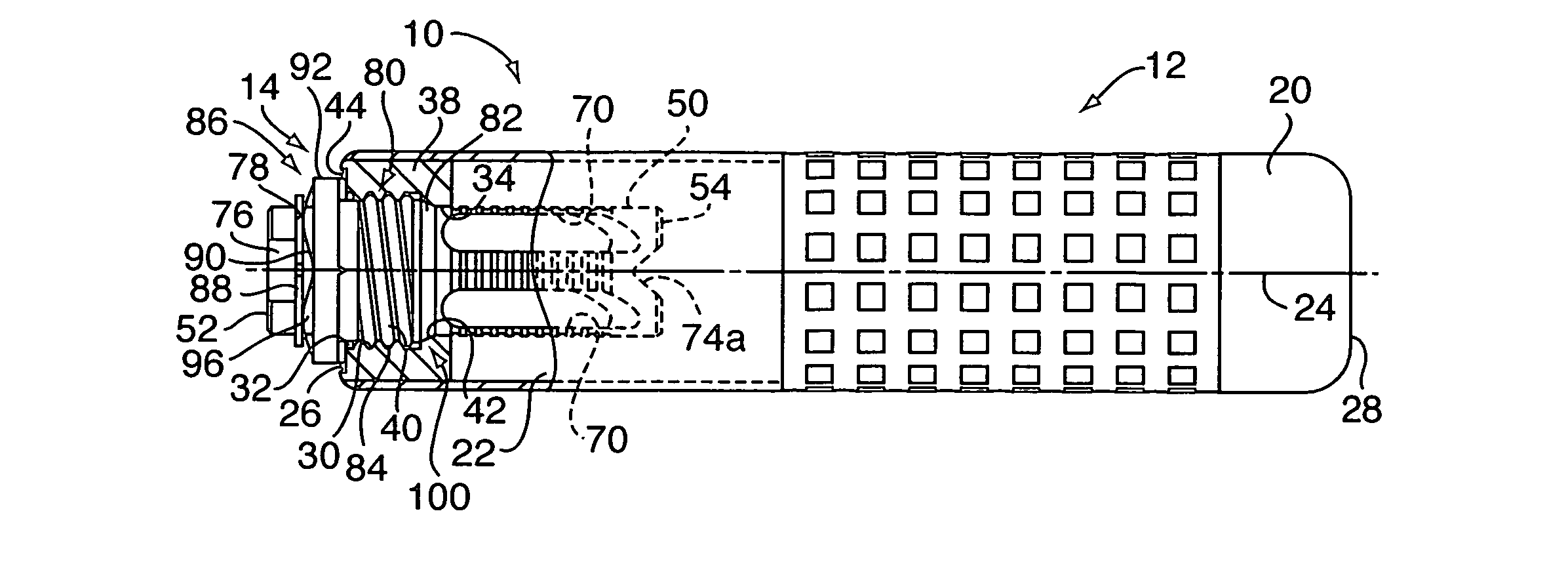
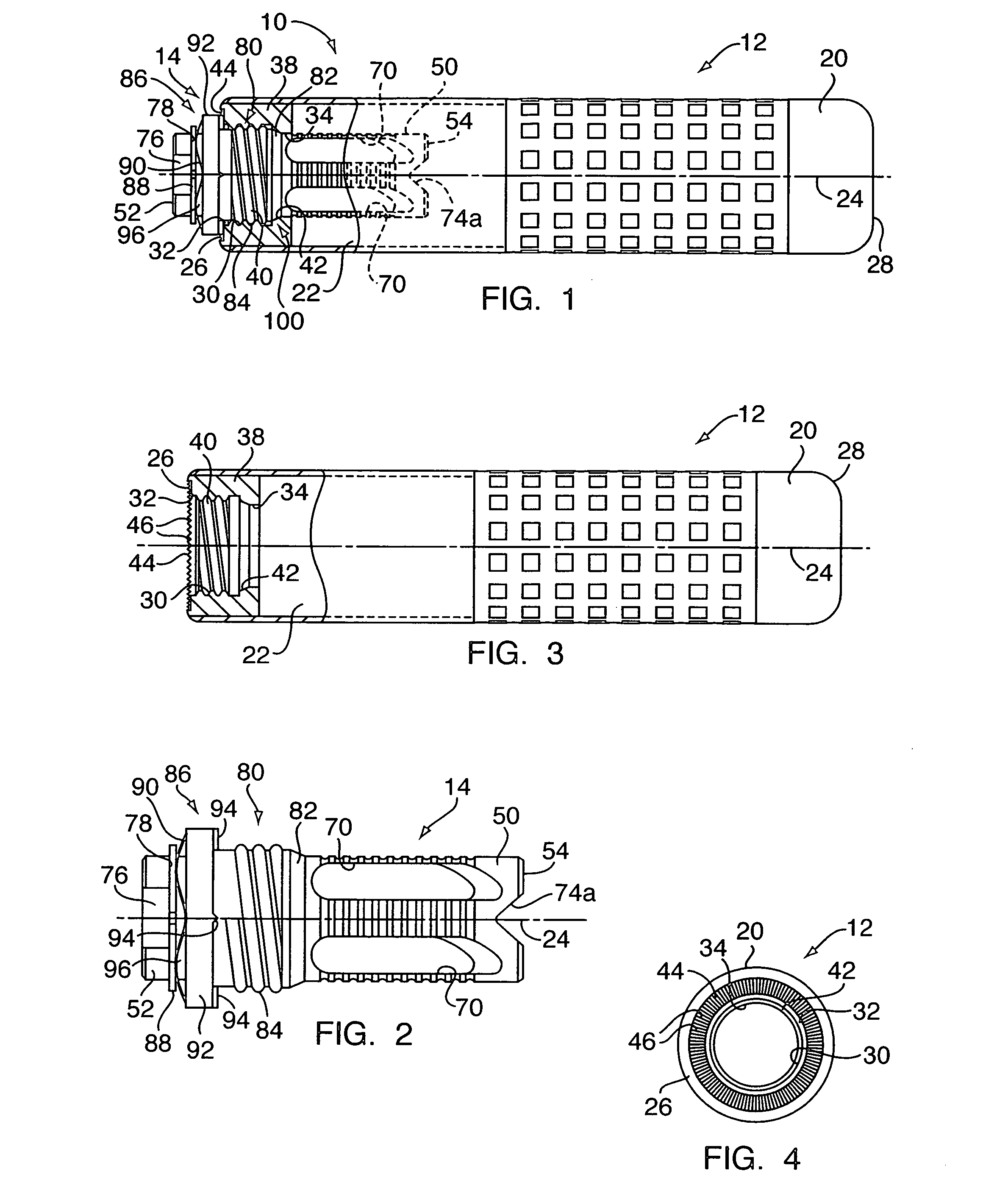
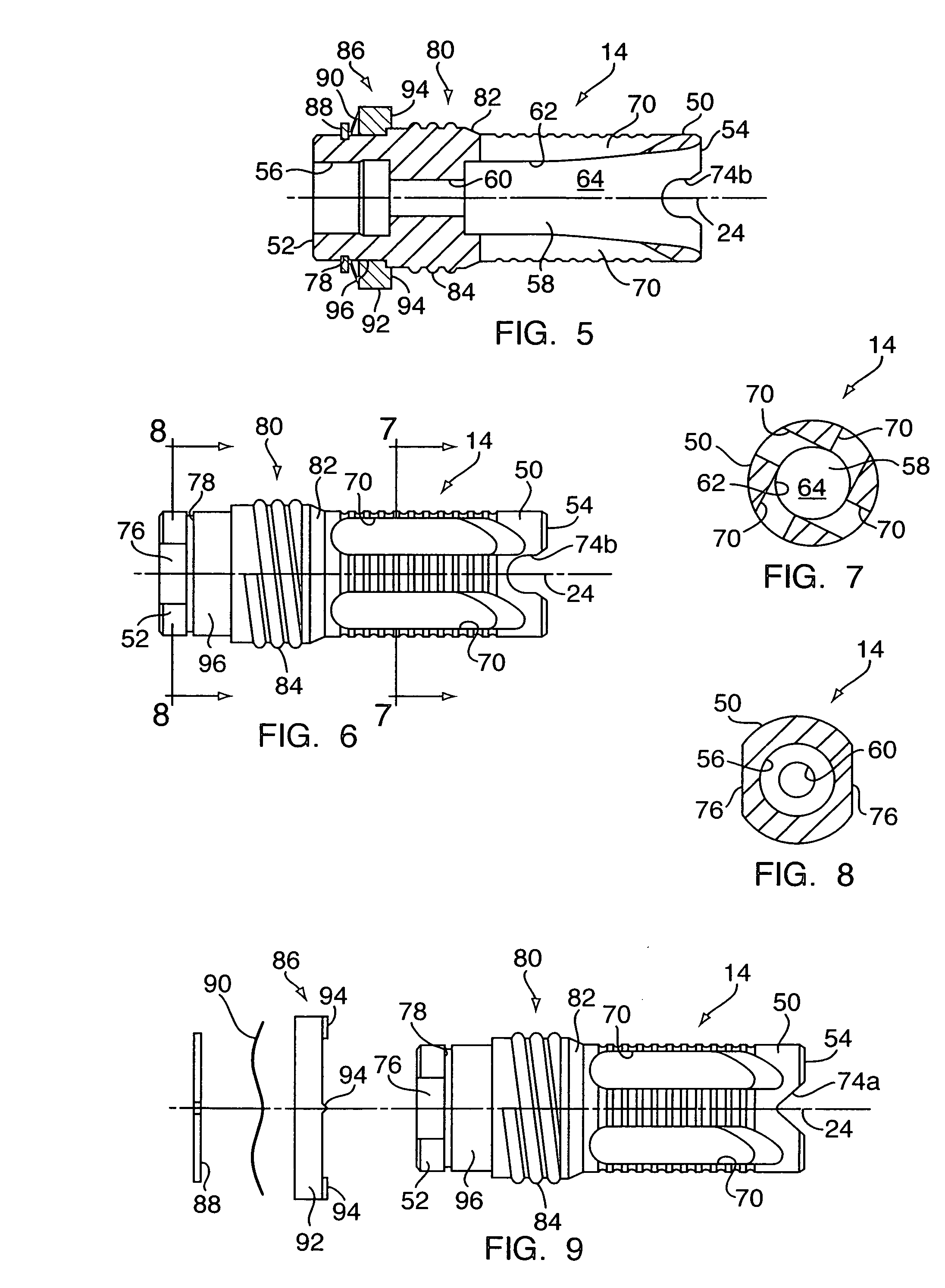
[0028]Referring to FIG. 1, a muzzle attachment system 10 according to an embodiment of the present invention, includes a silencer 12, also known as a sound suppressor, and a flash suppressor 14. Referring to FIGS. 3 and 4, the silencer 12 has a cylindrical body 20, partially defining an interior volume 22, which interior volume 22 concentrically surrounds a firing axis 24 of a firearm (not shown). The cylindrical body 20 extends between a first end 26 and a second end 28, the first and second ends 26, 28 each disposed substantially perpendicularly to the firing axis 24.

[0029]In the vicinity of the first end 26, proximate to a muzzle (not shown) of the firearm when the silencer 12 is connected to the firearm, an internal passage 30 is defined within the cylindrical body 20. The internal passage 30 extends between a first passage opening 32 in the first end 26 and a second passage opening 34, the second passage opening 34 communicating with the internal volume 22. The internal passage...


PUM


Abstract

A muzzle attachment system for a firearm includes a muzzle attachment having a first engagement means, and a muzzle distal portion including a second engagement means, the second engagement means being complementary with the first engagement means. The first and second engagement means cooperate to releasably secure the muzzle attachment to the muzzle distal portion. The first and second engagement means preferably include complementary coarse threaded engagement portions, an annular grooved surface having a plurality of grooves, a grooved surface engagement mechanism, and first and second position stops that abut to form a gas seal. The muzzle distal portion is preferably a flash suppressor, including at least two elongated ports substantially equally skewed from normal relative to a firing axis of the firearm, and substantially evenly distributed around the circumference of the flash suppressor.

Description

[0001]This application claims the benefit of Provisional Application No. 60 / 764,166, filed Jan. 31, 2006, the contents of which are herein incorporated by reference in their entirety.BACKGROUND[0002]A variety of devices have been developed for use in connection with the muzzle of a firearm. These devices, or muzzle attachments, include silencers, rocket and / or grenade launchers, line launchers, and the like. Because the circumstances under which a firearm is being used are liable to change quickly, it is desirable that the muzzle attachments and / or the corresponding firearm be adapted to allow rapid and reliable securing and removal of the muzzle attachments.[0003]The reliability of the connection of the muzzle attachment and muzzle, and the ease or quickness with which the muzzle attachment is secured and removed, tend to provide competing objectives in the design of a muzzle attachment system. For example, large numbers of fine threads and locking pins typically provide a very rel...

Claims


Application Information

Patent Timeline
Patent Type & Authority Applications(United States)
IPC IPC(8): F41A21/34F41A21/32
CPCF41A21/34F41A21/325
Inventor GRAHAM, JAMES J.
Owner YANKEE HILL MACHINE
Why Eureka
Try Eureka