Solar concentrator

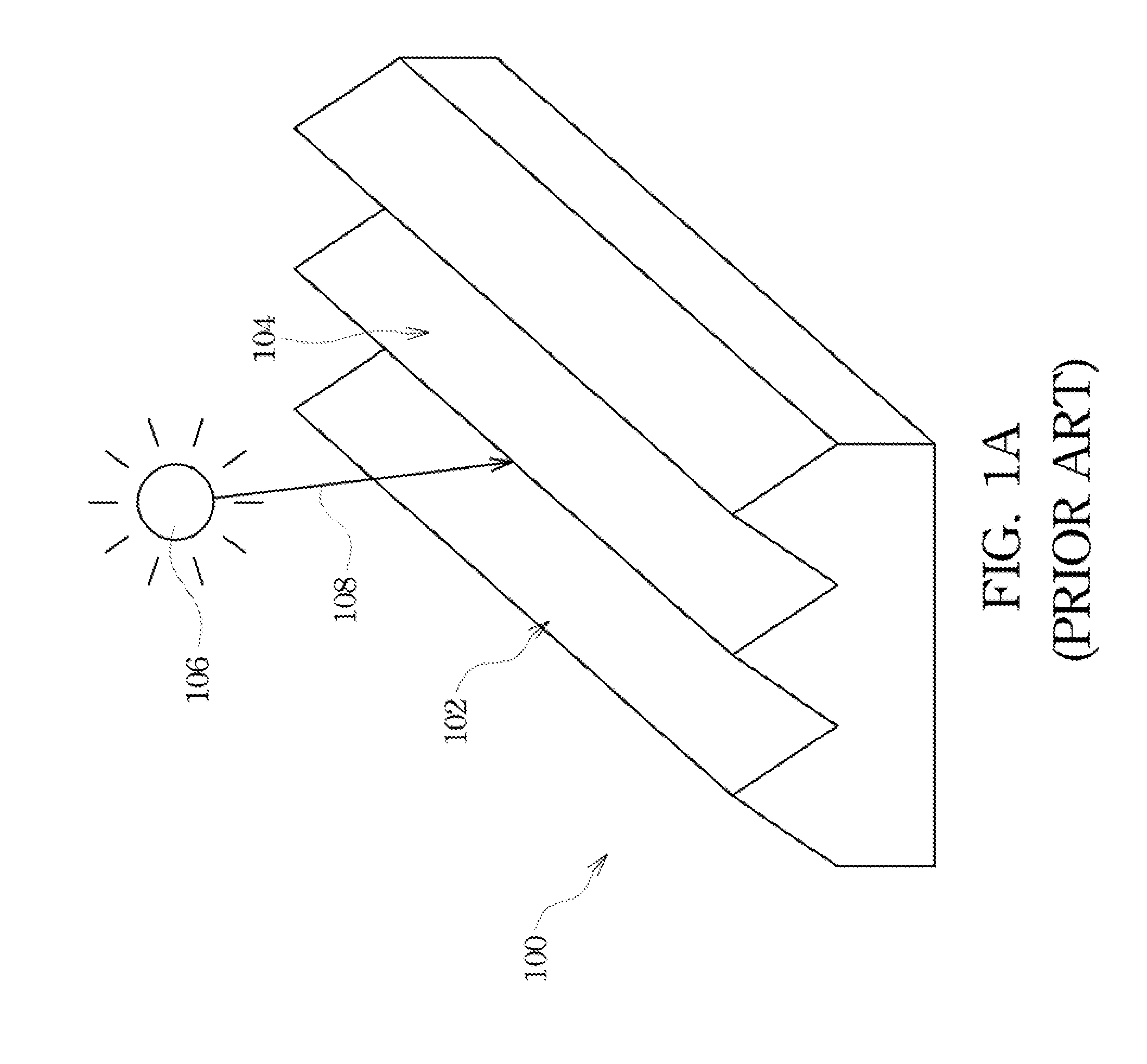
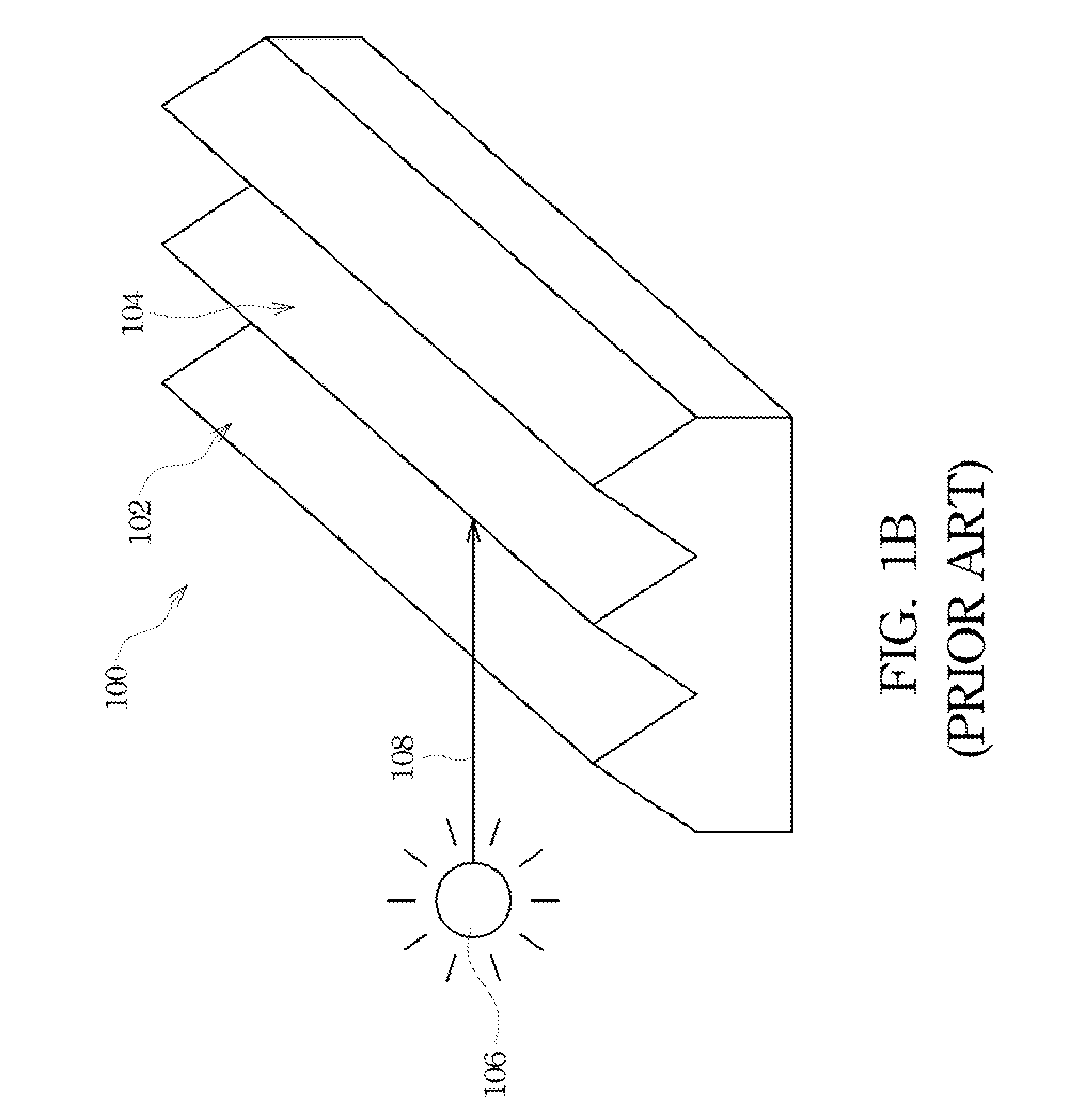
a solar concentrator and solar energy technology, applied in solar heat systems, pv power plants, light and heating equipment, etc., can solve the problems of inability to achieve good light-collecting effect of conventional solar concentrators b>100/b>, and achieve superior light-collecting ability and the effect of extending the range of incident light collection

Inactive Publication Date: 2010-09-16
NAT CHENG KUNG UNIV
View PDF12 Cites 13 Cited by
  • Summary
  • Abstract
  • Description
  • Claims
  • Application Information

AI Technical Summary

Benefits of technology

[0009]Therefore, one aspect of the present invention is to provide a solar concentrator, in which its plane includes a plurality of concentrating elements, and each concentrating element inclu

Problems solved by technology

As the earth resources are wasted and the technology is developed, the shortage of the international energy resources is induced.
Ther

Method used


Image

  • Solar concentrator
  • Solar concentrator
  • Solar concentrator

Examples


Embodiment Construction

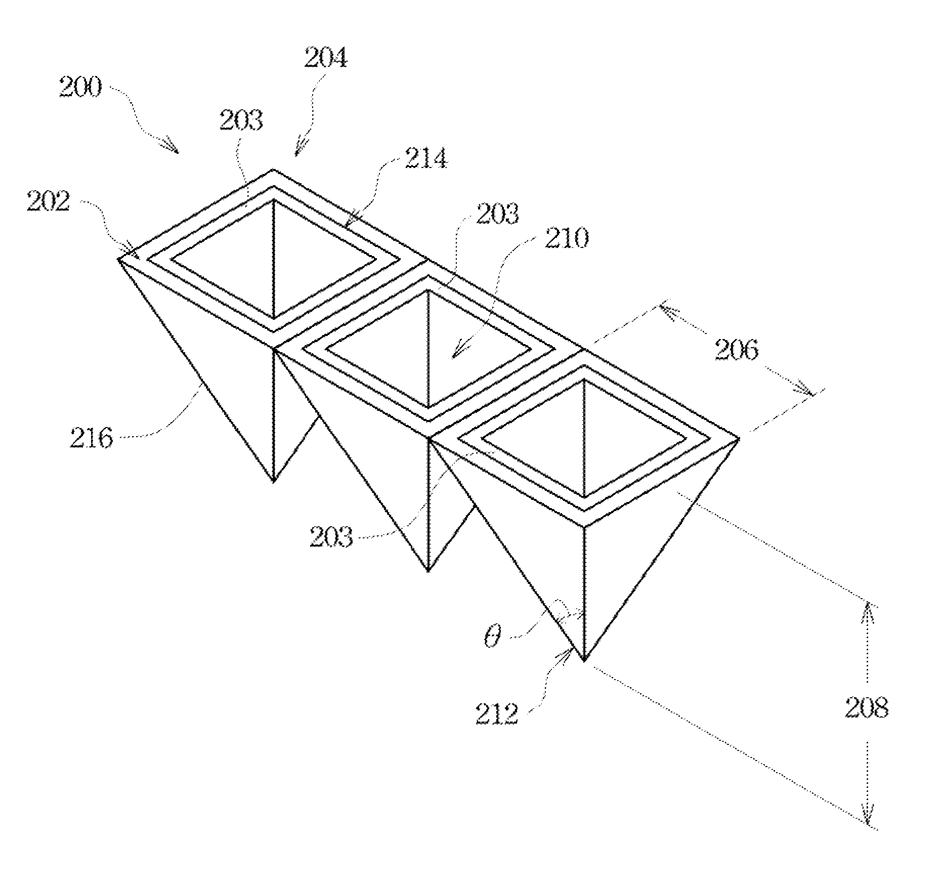
[0037]Refer to FIG. 2. FIG. 2 is a three-dimensional drawing of a solar concentrator in accordance with an embodiment of the present invention. In the exemplary embodiment, a solar concentrator 200 of a solar cell mainly includes a plane 202. The material of the plane 202 may be any material, such as glass, a steel material or a plastic material. The plane 202 includes a plurality of concentrating elements 204. An inner side surface of each concentrating element 204 is covered with one or more photoelectric conversion layers 203. The photoelectric conversion layer 203 has an ability of absorbing light to generate electric energy. In one embodiment, the plane 202 may be a monolithic structure, and the concentrating elements 204 are formed in the plane 202. In another embodiments, the plane 202 is not a monolithic structure and is formed by combining the concentrating elements 204.

[0038]Each concentrating element 204 includes a hollow taper 216, wherein each hollow taper 216 has an op...


PUM


Abstract

A solar concentrator is described. The solar concentrator includes a plane including a plurality of concentrating elements, wherein each concentrating element includes a hollow taper including a first opening; and at least one photoelectric conversion layer covering inner side surfaces of the concentrating elements.

Description

RELATED APPLICATIONS[0001]This application claims priority to Taiwan Application Serial Number 98108494, filed Mar. 16, 2009 and Taiwan Application Serial Number 98130094, filed Sep. 7, 2009, which are herein incorporated by reference.FIELD OF THE INVENTION[0002]The present invention relates to a solar device, and more particularly to a solar concentrator.BACKGROUND OF THE INVENTION[0003]As the earth resources are wasted and the technology is developed, the shortage of the international energy resources is induced. In view of this, various countries in the world positively invest in the development of various alternative sources of energy. Among the alternative sources of energy, because sunlight is inexhaustible in supply and always available for use, it pays close attention to the development of solar energy apparatus for generating electric power, such as a solar cell.[0004]A solar cell is a renewable energy that can directly generate electric power by the interaction of the sunl...

Claims


Application Information

Patent Timeline
IPC IPC(8): H01L31/052H01L31/00F24S23/00F24S23/70
CPCF24J2/06F24J2/10F24J2/1047H01L31/0547Y02E10/52H01L31/054H01L31/0543F24J2002/108F24S23/00F24S23/70F24S23/80F24S2023/872
Inventor HONG, CHAU-NANCHU, SHU-CHUNYU, WANG-CHIEHCHANG, SHAN-BINHON, MIN-HSIUNG
Owner NAT CHENG KUNG UNIV
Why Eureka
Try Eureka