
Oven Steam Generator Systems and Methods

a technology of steam generator and oven, which is applied in the field of steam oven, can solve the problems of affecting the operation of steam cooking vessels, affecting the quality of steam cooking, etc., and achieves the effect of building up pressure and maintaining inside the oven

Active Publication Date: 2010-09-16
SAFRAN CABIN GALLEYS US INC
View PDF31 Cites 25 Cited by
  • Summary
  • Abstract
  • Description
  • Claims
  • Application Information

AI Technical Summary

Problems solved by technology

One downside associated with injection systems is that over time, water calcification can build up on the heating elements and fan elements.
A further downside of these systems is that the user needs to wait until the oven reaches a certain temperature before the water can be injected with the desired effects, which may take longer than is often desired.
Additionally, systems using these methods are typically pressurized systems, meaning that pressure must be built up and maintained inside the oven.
They also tend to be more expensive, heavier, and create more liability during use.
For example, when the user is ready to open the door, the pressure in the oven must be completely relieved before the door can be opened; opening the door in the middle of a cooking cycle can be quite dangerous, resulting in scalding the user or others in the vicinity.
Additionally, pressurized steam ovens cannot be used if the seals are weakened or damaged or otherwise show signs of wear, adding to maintenance expense.
One downside associated with drip systems is that due to the use of two heaters, they generate more heat loss from the unit, they require more power consumption, and they tend to be heavier than other types of steam ovens.
Such systems are typically unpressurized ovens, which means that pressure is not maintained inside the oven.
These ovens do not lend themselves to use onboard aircraft or other transport vehicles, due to the extra weight and larger size associated with these types of ovens.
They also require a great deal more power consumption due to the use of a separate steam generator system.

Method used


Image

  • Oven Steam Generator Systems and Methods
  • Oven Steam Generator Systems and Methods
  • Oven Steam Generator Systems and Methods

Examples


Embodiment Construction

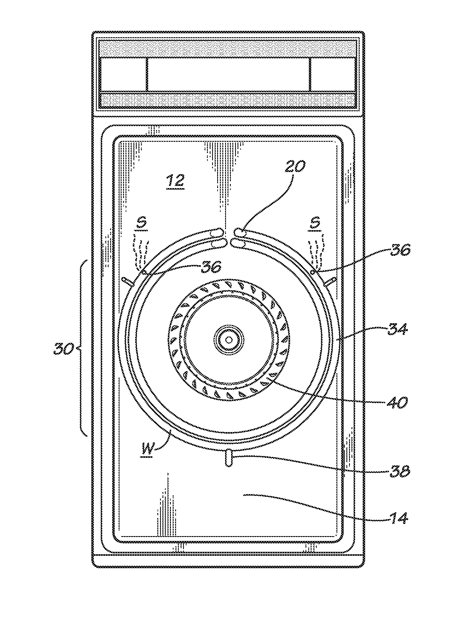
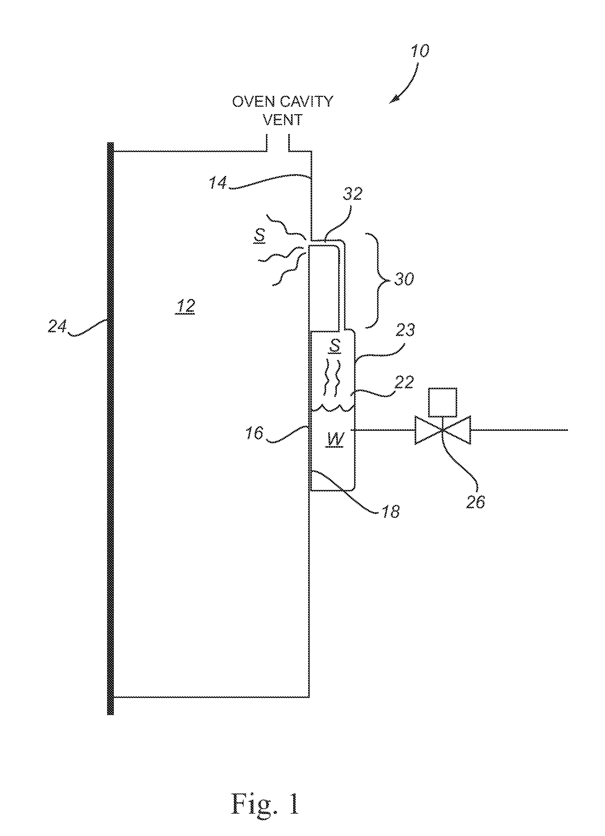
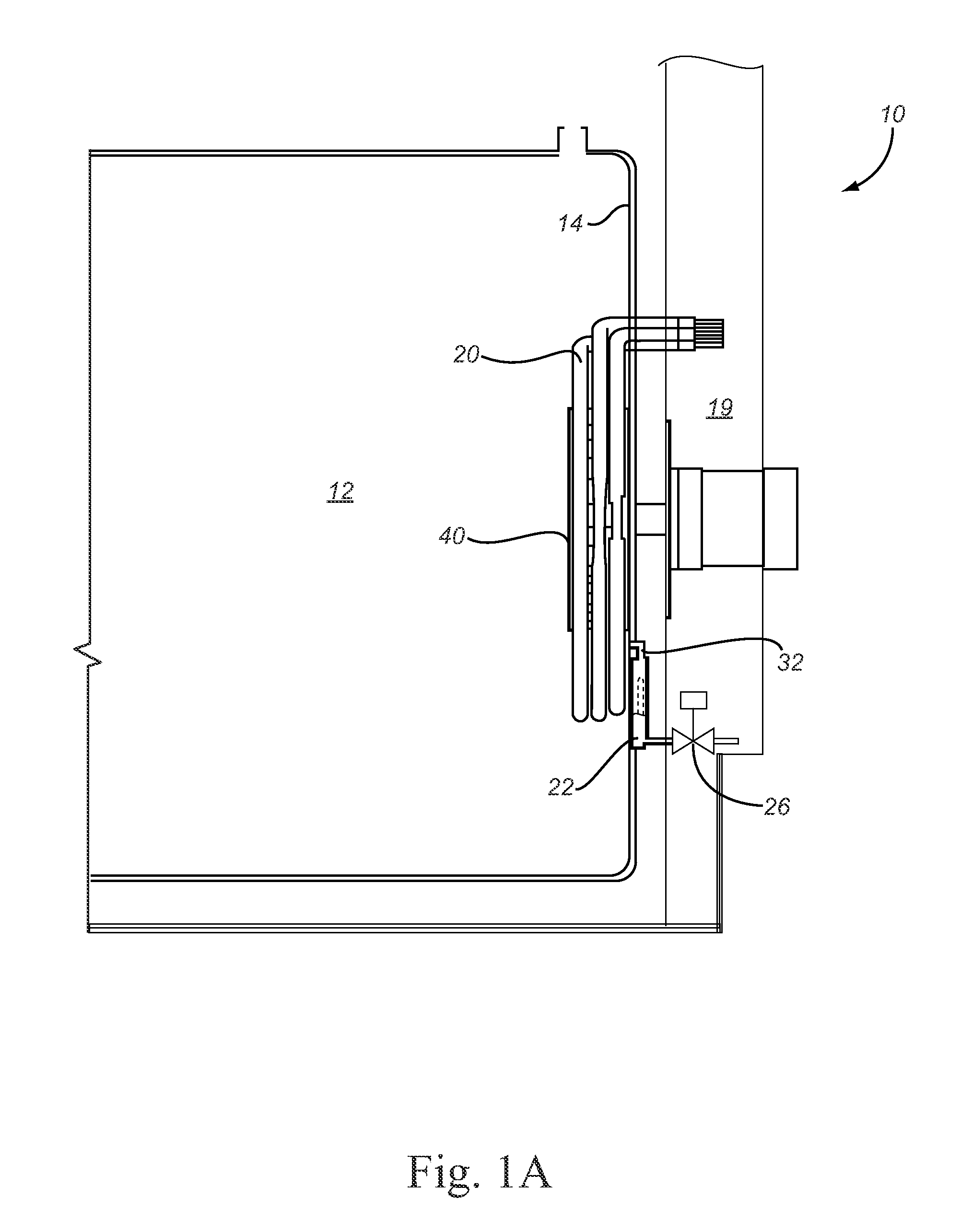
[0022]Embodiments of the present invention provide steam ovens that generate steam by using heat from an existing oven heat generating system (i.e., one that is already a part of the steam oven), which eliminates the use of a separate electrical heater. The generated heat may be used to directly heat water in the water reservoir system, or to indirectly heat water in the water reservoir system. Indirect heating may occur by transfer of heat to an oven liner, which then transfers its heat to a water reservoir mounted thereto, such that the water in the water reservoir is heated and converted to steam using the lost heat from the oven inner liner. A further embodiment uses existing heater elements that are present inside the oven cavity and provides a water reservoir tube that closely conforms to the heater elements, such that heat is transferred to the water reservoir tube, and consequently to the water contained therein, forming steam that is delivered to the oven cavity.

[0023]For e...


PUM


Abstract

Embodiments of the present invention relate generally to steam ovens, and particularly to steam ovens configured to generate and deliver steam directly to the oven using a water reservoir in close proximity to an existing oven heat generating system. The steam ovens described may be designed so that they inject steam directly into the oven cavity, and in some instances, generate the steam directly in the oven cavity as well. Certain embodiments are designed with a water reservoir in close proximity to an oven heat generating system such that water in the reservoir is heated, turned to steam, and delivered to the oven cavity via a steam delivery system.

Description

[0001]This application claims the benefit of U.S. Provisional Application Ser. No. 61 / 145,123, filed Jan. 16, 2009 titled “Steam Generation Methods and Apparatus Using Oven Heat,” U.S. Provisional Application Ser. No. 61 / 170,350, filed Apr. 17, 2009 titled “Steam Oven Generator,” and U.S. Provisional Application Ser. No. 61 / 170,372, filed Apr. 17, 2009 titled “Steam Oven Generator Control System,” the entire contents of each of which are hereby incorporated by reference.FIELD OF THE INVENTION[0002]Embodiments of the present invention relate generally to steam ovens, and particularly to steam ovens configured to generate and deliver steam directly to the oven using a water reservoir in close proximity to an existing oven heat generating system. The steam ovens described may be designed so that they inject steam directly into the oven cavity, and in some instances, generate the steam directly in the oven cavity as well. Certain embodiments are designed with a water reservoir in close ...

Claims


Application Information

Patent Timeline
Patent Type & Authority Applications(United States)
IPC IPC(8): A21B3/00A21B1/22
CPCB64D11/04F24C15/327F22B1/284Y10T137/7837Y10T137/0396
Inventor BOUBEDDI, ABDELAZIZMILLER, PAUL E.
Owner SAFRAN CABIN GALLEYS US INC
Learn More