Rotary Blow Molding Machine with Movable Clamp Assemblies and Method

a technology of clamp assembly, which is applied in the field of continuous rotary blow molding machine, can solve the problems of increasing the cost of blow molding bottles, waste of flash, and having to be discarded, and achieves the effect of reducing flash and simplifying parison extrusion equipmen

Inactive Publication Date: 2010-09-16
GRAHAM ENG CORP
View PDF24 Cites 13 Cited by
  • Summary
  • Abstract
  • Description
  • Claims
  • Application Information

AI Technical Summary

Benefits of technology

[0004]The invention is an improved rotary blow molding machine in which mold clamp assemblies including molds are movably mounted on a continuously rotating frame. The blow molding machine includes an assembly drive for shifting the mold clamp assemblies between upstream and downstream positions on the frame as the frame continuously rotates downstream during blow molding. Flash is reduced. Blow pins may be used to form the necks of bottles. Parison extrusion equipment is simplified.

Problems solved by technology

The flash is waste and must be discarded.
The flash trimming and machining operations increase the cost of blow molded bottles.

Method used


Image

  • Rotary Blow Molding Machine with Movable Clamp Assemblies and Method
  • Rotary Blow Molding Machine with Movable Clamp Assemblies and Method
  • Rotary Blow Molding Machine with Movable Clamp Assemblies and Method

Examples


Embodiment Construction

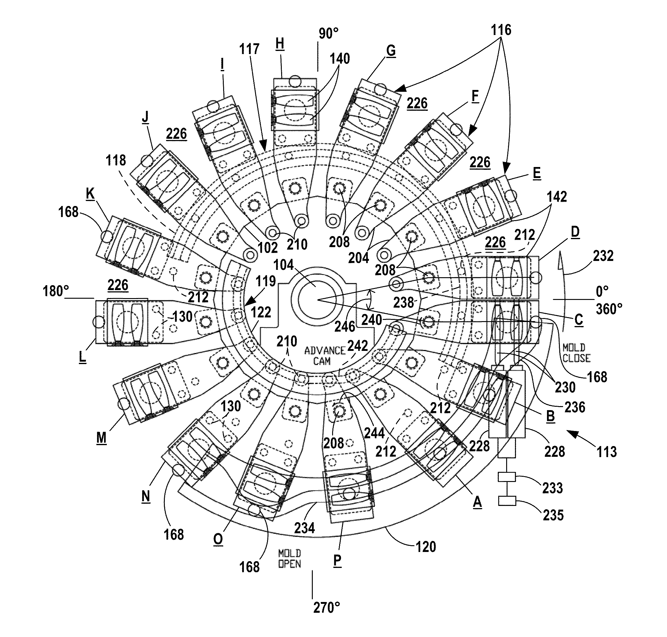
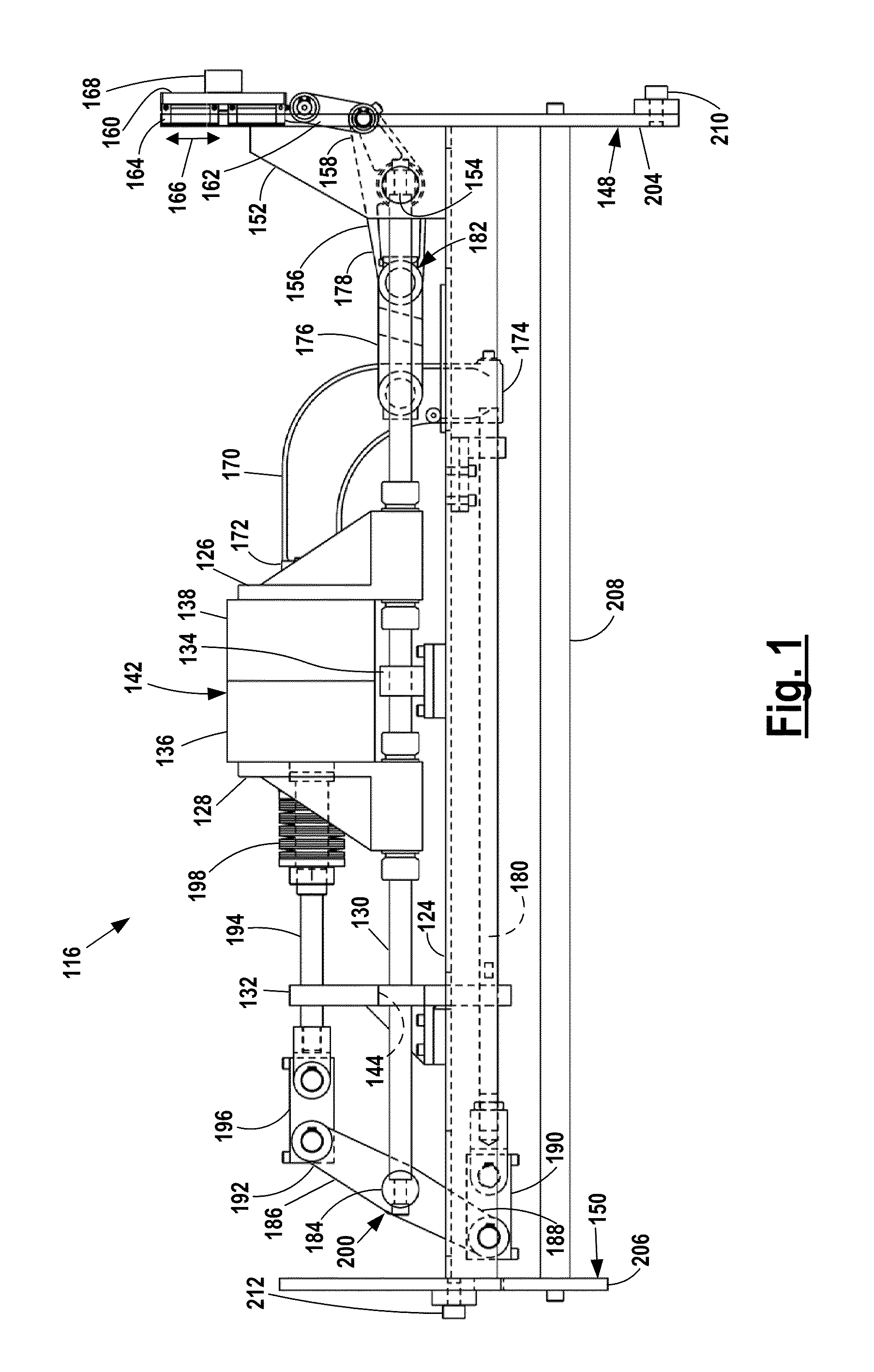
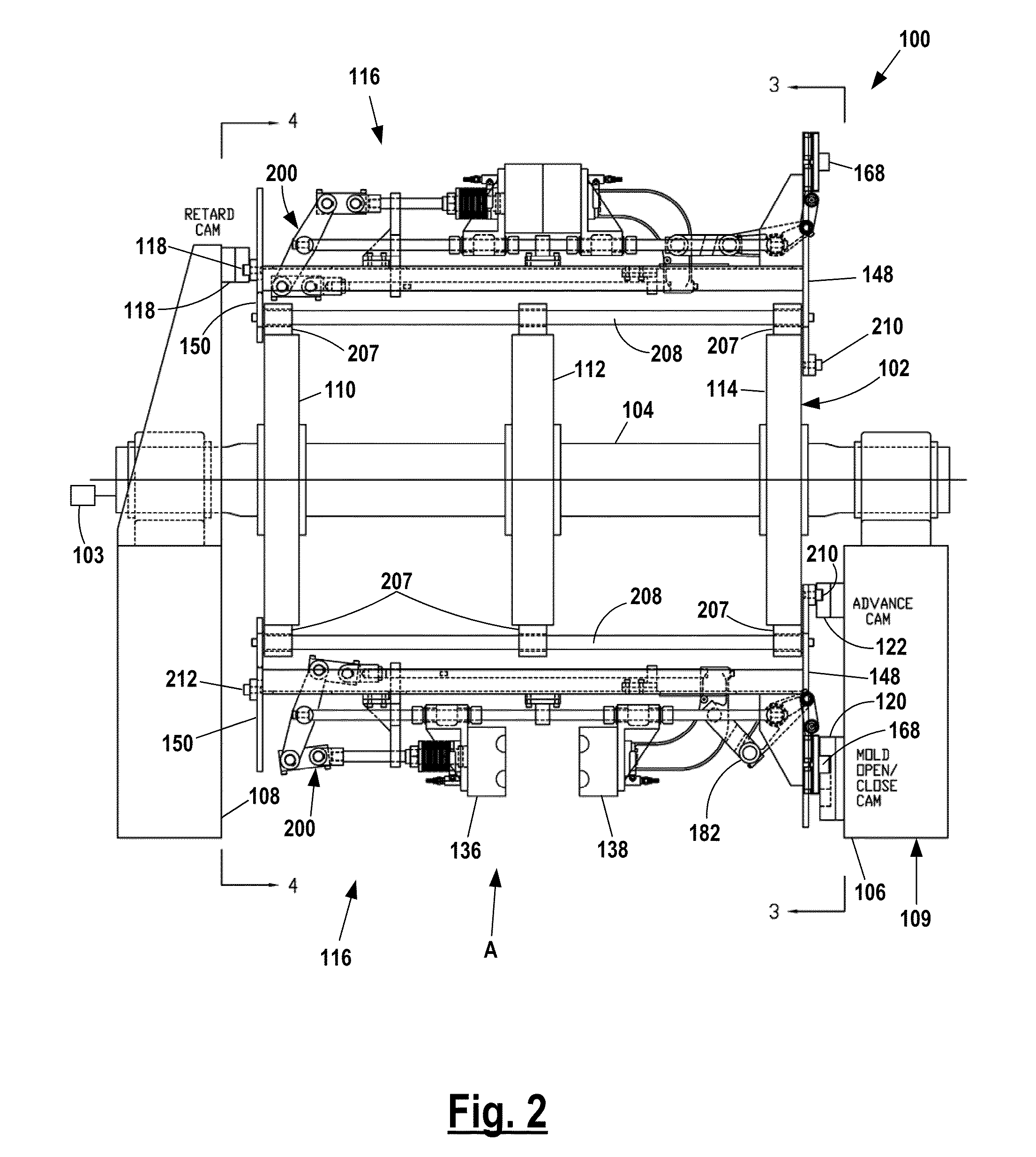
[0016]FIGS. 1 to 6 illustrate a rotary blow molding machine 100 including a rotary frame 102 having a horizontal main shaft 104 with ends journaled in bearings mounted on shaft supports 106 and 108. Three circular mounting plates 110, 112 and 114 are mounted on and rotate with shaft 104. Sixteen mold clamp assemblies 116 are mounted on the plates at circumferential locations spaced around the frame.

[0017]The rotary frame 102 and assemblies 116 are continually rotated around the axis of the main shaft 104 by a conventional drive 103, which may be an electric motor in the direction of arrow 232 shown in FIGS. 3 and 4. Rotation of frame 102 continuously moves the mold clamp assemblies 116 downstream past extrusion, blow molding, cooling and ejection stations spaced around the machine.

[0018]Shaft supports 106 and 108 form parts of a stationary main frame 109. Partial circumferential upstream shift or retard cam 118 is mounted on support 108 facing plate 110. Partial circumferential mold...


PUM

PropertyMeasurementUnit
circumferenceaaaaaaaaaa
distancesaaaaaaaaaa
speedaaaaaaaaaa

Abstract

A continuous blow molding machine includes a mechanism for shifting molds upstream during closing to reduce between-mold flash.

Description

FIELD OF THE INVENTION[0001]The invention relates to continuous rotary blow molding machines with mold clamps and to methods for blow molding articles.DESCRIPTION OF THE PRIOR ART[0002]Conventional continuous rotary blow molding machines extrude one or more continuous parisons for capture in cavities in adjacent molds for blow molding. Mold flash extends between mold cavities in adjacent molds and typically includes a blow dome. The flash must be cut away from the bases and necks of the bottles. The cut at the neck must be machined to form a flat surface perpendicular to the neck axis for making a seal with an applied closure. The flash is waste and must be discarded. The flash trimming and machining operations increase the cost of blow molded bottles.[0003]In continuous rotary blow molding machines, one flow head continuously extrudes a parison for capture in each mold cavity in each mold. Parisons must be extruded at the circumferential speed of each mold cavity. The cavities are ...

Claims


Application Information

Patent Timeline
Patent Type & Authority Applications(United States)
IPC IPC(8): B29C49/04
CPCB29C49/04B29C2049/048B29C2049/044B29C49/36B29C2049/503B29C49/42B29C49/04102B29C49/04108B29C49/42386B29C2049/787B29C2049/7873
Inventor OLES, PAUL M.
Owner GRAHAM ENG CORP
Why Eureka
Try Eureka