Recording device, control method, and recording medium

a technology of recording device and control method, applied in the direction of printing, other printing apparatus, etc., to achieve the effect of reducing the variation in the rotation amount of the transfer roller

Active Publication Date: 2010-09-16
RICOH KK
View PDF8 Cites 5 Cited by
  • Summary
  • Abstract
  • Description
  • Claims
  • Application Information

AI Technical Summary

Benefits of technology

[0011]Because of these reasons, the present inventors recognize that a need exists for a recording device, a control method and a program by which the variation in the rotation amount of a transfer roller is reduced along the sub-scanning direction without moving a recording head detection device.

Problems solved by technology

However, the system of conveying a recording medium by transfer rollers involves a problem such that the assembly and eccentricity of the transfer rollers affect transfer (conveyance) of the recording medium.

Method used


Image

  • Recording device, control method, and recording medium
  • Recording device, control method, and recording medium
  • Recording device, control method, and recording medium

Examples


first embodiment

Schematic Structure of Mechanism of Recording Device

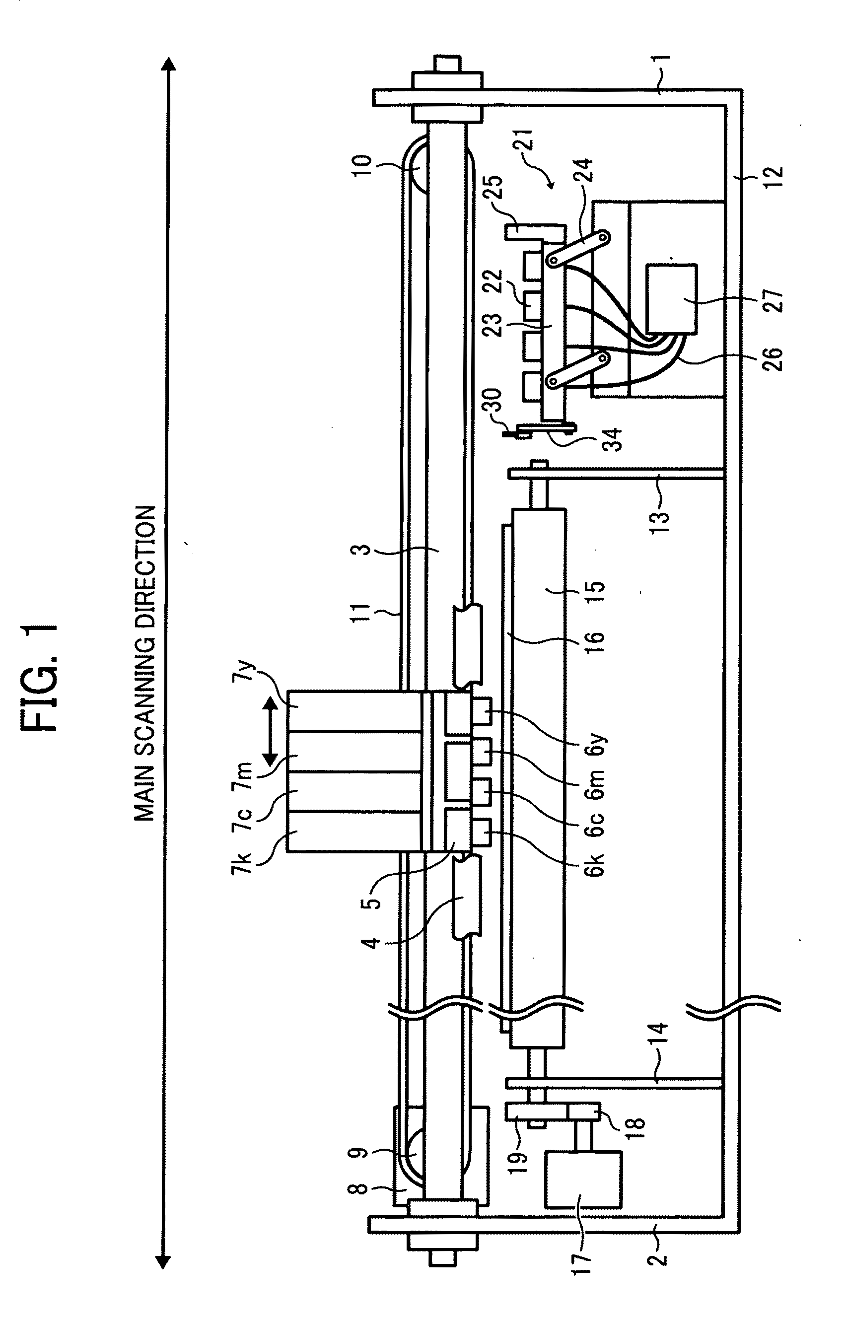
[0042]The schematic structure of the mechanism of the recording device of this embodiment is described below in detail with reference to FIG. 1.

[0043]The recording device of this embodiment includes a main support guide rod 3 and a sub-support guide rod 4 provided in substantially parallel thereto between side plates 1 and 2. The rods 3 and 4 support a carriage 5 such that the carriage 5 slidably moves in the main scanning direction.

[0044]The carriage 5 has four recording heads 6y, 6m, 6c and 6k that discharge yellow (Y) ink, magenta (M) ink, cyan (C) ink, and black (Bk), respectively, with the discharging surfaces (nozzle phase) thereof downward. In addition, the carriage 5 includes replaceable four ink cartridges 7 (which means any or all of 7y, 7m. 7c and 7k) provided above the recording head 6 (which means any or all of 6y, 6m. 6c and 6k). The ink cartridge 7 supplies respective inks to the four recording heads 6. The carriage ...

second embodiment

[0134]The second embodiment is described next.

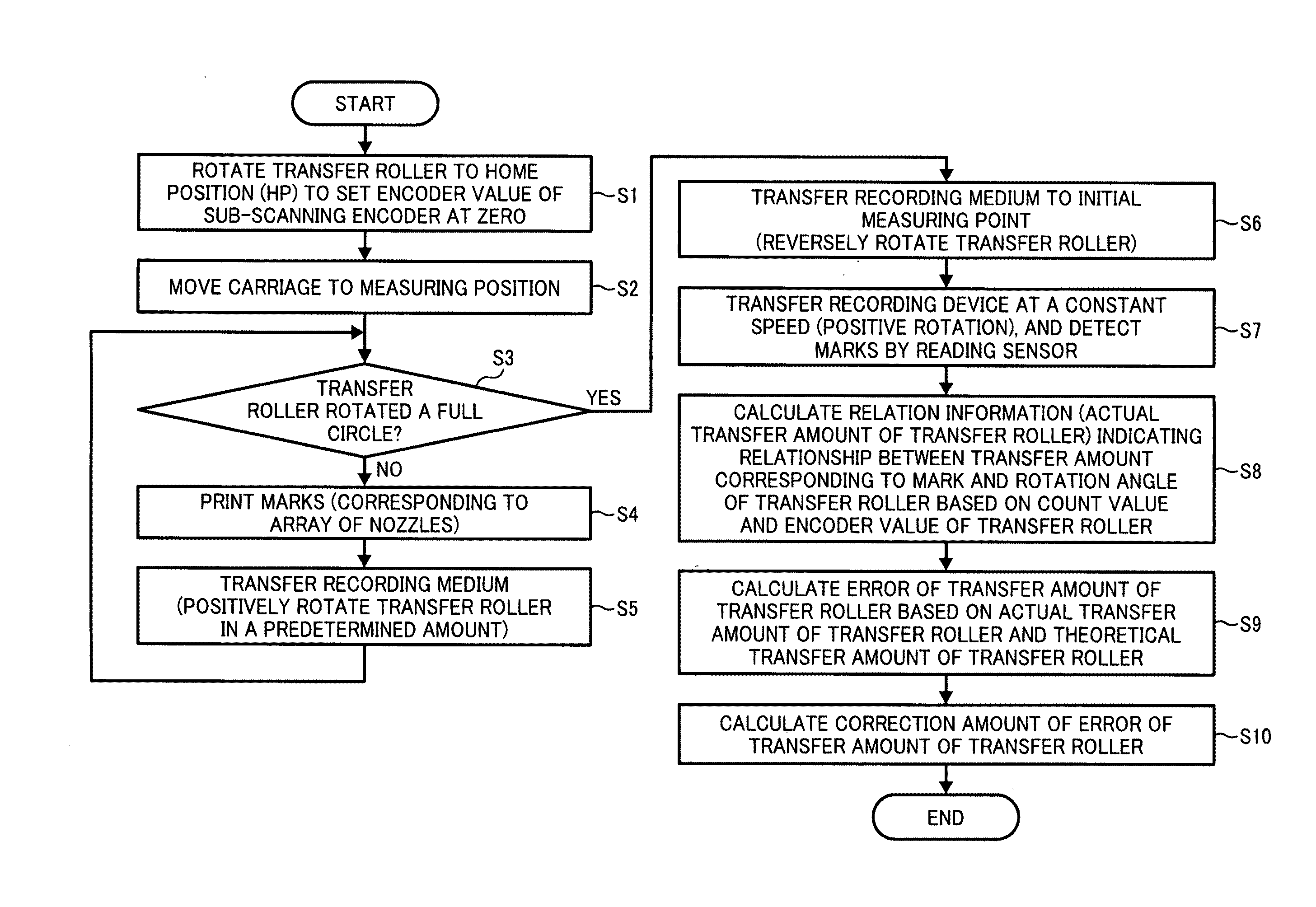
[0135]In the first embodiment, as illustrated in FIG. 19, the printing process of the marks 101 is repeated (from Step S3 / No, to S4 and to S5) until the transfer roller is determined to rotate at least a full circle. In addition, when the transfer roller is determined to rotate at least a full circle (Step S3 / Yes), the transfer roller 15 is reversely rotated to move back the recording medium 16 to the measuring start position (Step S6) and then the marks 101 are detected (Step S7) followed by calculation of the correction amount of the difference of the transfer amount by the transfer roller 15 according to the detection results of the marks 101 (Step S8 to S10).

[0136]In the second embodiment, as illustrated in FIG. 16, before he transfer roller is determined to rotate at least a full circle (before Step S3 / Yes), the printing process of the marks 101 (Step S′4) and the detection process thereof (Step S′5) are alternately performed. When ...


PUM


Abstract

A recording device including a carriage head, a recording head installed onto the carriage head, the recording head having an array of nozzles that discharges ink on a recording medium, a transfer roller that transfers the recording medium in a direction along the array of nozzles, a control device that controls rotation of the transfer roller, a first detection roller that detects a rotation position of the transfer roller, and a second detection device that detects a mark printed on the recording medium by the recording head, the control device including a print control device that controls printing the marks on the recording medium in the direction along the array of nozzles from the array of nozzles of the recording head while the carriage and the transfer roller remain still, a calculation device that calculates a correction amount for use in correction of a rotation angle of the transfer roller according to a difference between an actual transfer amount of the recording medium by the transfer roller at a predetermined rotation position obtained by detection of the marks by the second detection device while the transfer roller is in rotation and a theoretical transfer amount of the recording medium at the predetermined rotation position, and a correction device that corrects the rotation angle of the transfer roller using the correction amount.

Description

BACKGROUND OF THE INVENTION[0001]1. Field of the Invention[0002]The present invention relates to recording devices such as an ink jet printer.[0003]2. Discussion of the Background[0004]A recording device employing an ink jet system records an image on a recording medium by discharging ink from a recording head while moving the recording head back and forth in the primary scanning direction to cause the ink to attach to the recording medium. Then, the recording medium is conveyed in the sub-scanning direction by transfer rollers, etc. to repeat recording in the main scanning direction and form the image on the recording medium.[0005]However, the system of conveying a recording medium by transfer rollers involves a problem such that the assembly and eccentricity of the transfer rollers affect transfer (conveyance) of the recording medium. When the transfer amount of the recording medium varies, the image is formed at a position different from the target (ideal, theoretical) recording ...

Claims


Application Information

Patent Timeline
Patent Type & Authority Applications(United States)
IPC IPC(8): B41J29/38
CPCB41J29/38
Inventor KOBAYASHI, MASATOSAKURAI, YASUOSATOH, NOBUYUKIKIMURA, TOMONORISAKURADA, YUICHISUZUKI, ARATA
Owner RICOH KK
Why Eureka
Try Eureka