Combination structure of LED lighting device

a technology of led lighting and combination structure, which is applied in the field of led street lamps, can solve the problems of limited service life, disadvantageous influence on its service life, and disadvantageous mass production, and achieve the effects of shortened production time, reduced molding tool costs, and safer transportation

Inactive Publication Date: 2010-09-16
PYROSWIFT HOLDING CO LIMITED
View PDF1 Cites 70 Cited by
  • Summary
  • Abstract
  • Description
  • Claims
  • Application Information

AI Technical Summary

Benefits of technology

[0009]In comparison with the conventional LED lighting device, the lamp set composed of a lampshell and two covers brings lower costs of molding tools, a shortened production time and safer transportation. It can improve the yield rate of products and is helpful for mass production and assembly.

Problems solved by technology

For a conventional mercury-vapor streetlamp, the high heat resulting from a long use always makes its service life limited.
However, the heat generated from the LED will have disadvantageous influence on its service life.
It is disadvantageous to mass production because of high molding costs and long cycle time of manufacturing when the lamp set and the heat dissipating fins are formed as an integrated body by an aluminum-extruding process or a die casting process.
In addition, the finished productions tend to be damaged because of the collision during transportation.
All these factors will make the manufacturing costs rise.

Method used


Image

  • Combination structure of LED lighting device
  • Combination structure of LED lighting device
  • Combination structure of LED lighting device

Examples


Embodiment Construction

[0018]The technical characteristics, features and advantages of the present invention will become apparent in the following detailed description of preferred embodiments with reference to the accompanied drawings, and the preferred embodiments are used for illustrating the present invention only, but not intended to limit the scope of the present invention.

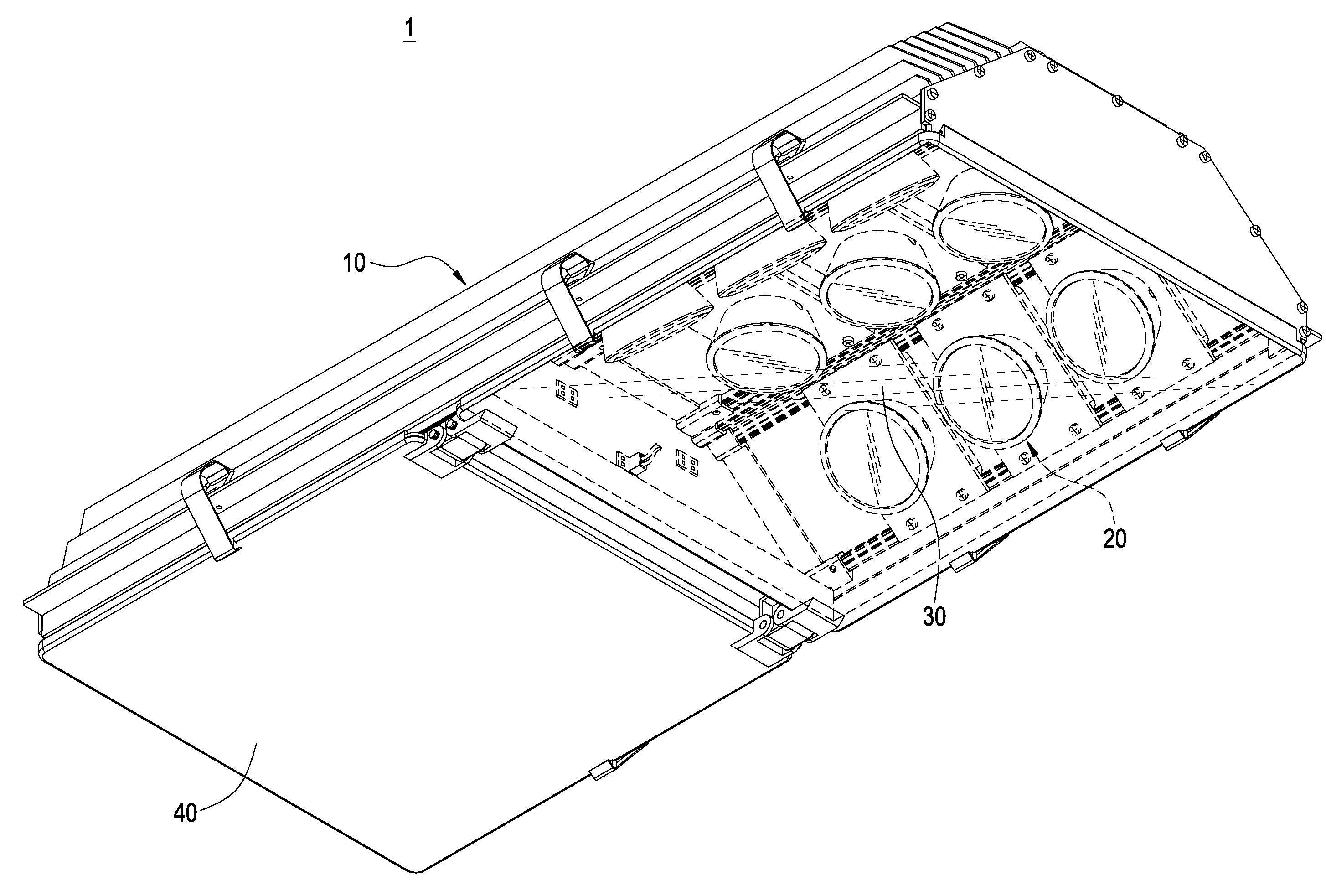
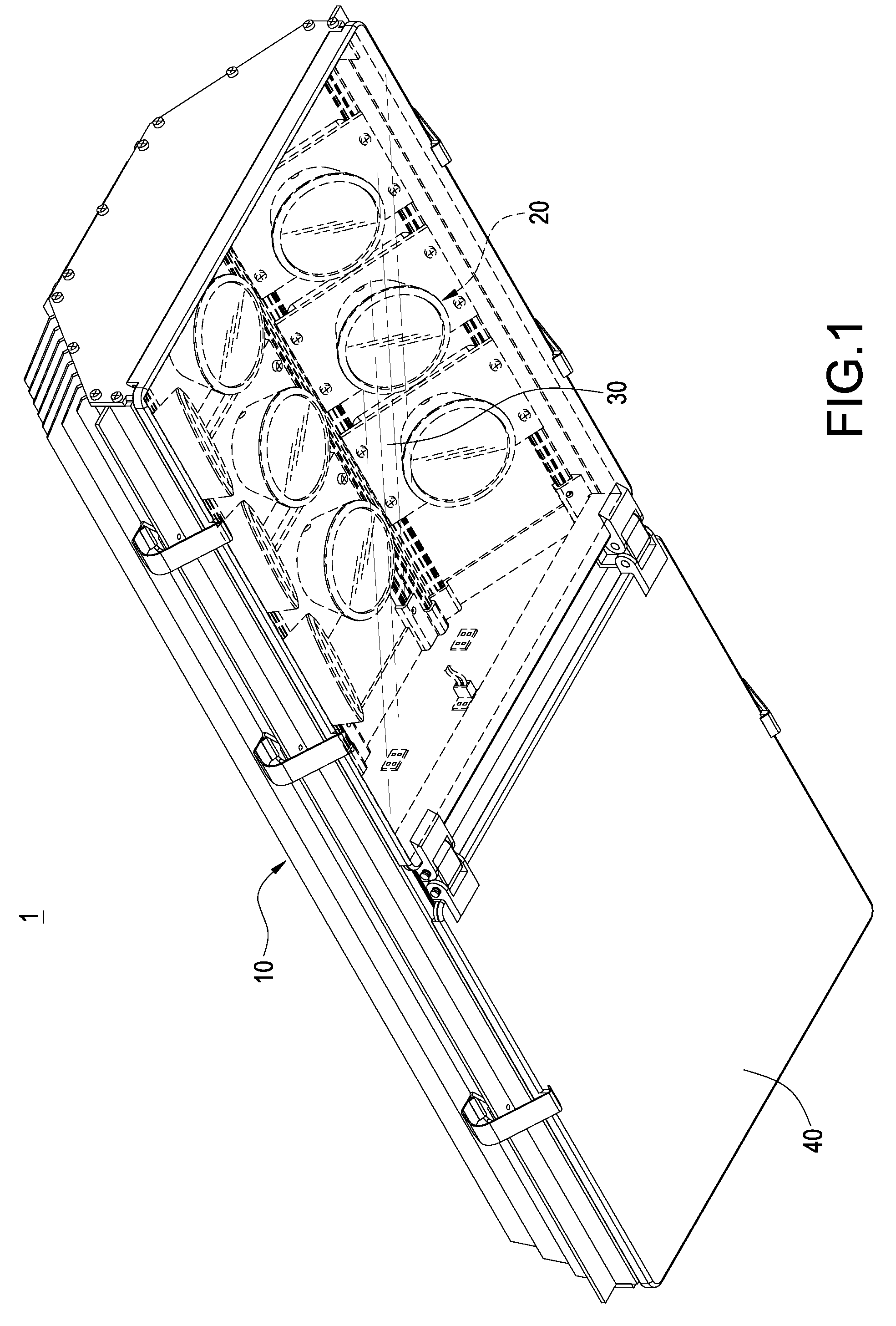
[0019]With reference to FIG. 1, the LED lamp 1 comprises a lamp set 10, a transparent cover 30 and an opaque cover 40. The lamp set 10 has a plurality of light-emitting modules 20 inside, and both the transparent cover 30 and the opaque cover 40 cover the lamp set 10.

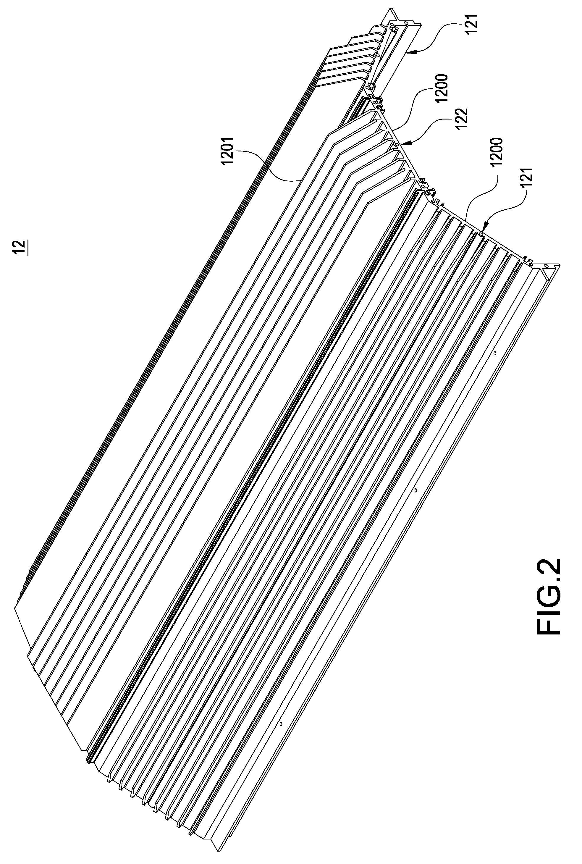
[0020]With further reference to FIGS. 2 to 4, the lamp set 10 is made of Aluminum. The lamp set 10 having an accommodating space 11 is a barlike hollow body composed of a lampshell 12 and two covers 13. The lampshell 12 is assembled by two pieces of lateral lampshell 121 and one piece of middle lampshell 122 sandwiched therebetween. The two lateral lampshells 121 incl...


PUM


Abstract

An LED lamp with lower manufacturing costs is disclosed. The LED lamp includes a lamp set, a plurality of light-emitting modules and a transparent cover. The lamp set having an accommodating space is a barlike body composed of a lampshell and two covers. The lampshell is constituted by two lateral lampshells and one middle lampshell connected therebetween. The lateral lampshells and the middle lampshell are connected together by a fixing structure. The two covers seal the front and rear sides of the lamp set separately. Furthermore, plural light-emitting modules are installed on the interior surface of the lampshell, and the transparent cover is fixed to cover the lamp set.

Description

BACKGROUND OF THE INVENTION[0001]1. Field of the Invention[0002]The present invention generally relates to a lighting device, and more particularly to a light emitting diode (LED) streetlamp.[0003]2. Description of Prior Art[0004]For a conventional mercury-vapor streetlamp, the high heat resulting from a long use always makes its service life limited. Because of its high power consuming and environmental pollution, it trends toward being replaced by a light emitting diode (LED) lighting device for advantages of high intensity, power saving and long service life, etc.[0005]However, the heat generated from the LED will have disadvantageous influence on its service life. The LED streetlamps usually employ heat dissipating devices for rapidly dissipating the heat. The heat dissipating devices of conventional LED streetlamps are provided with a plurality of heat dissipating fins on outer surfaces of the lamp bases for enhancing the heat dissipation efficiency by large heat dissipating ar...

Claims


Application Information

Patent Timeline
Patent Type & Authority Applications(United States)
IPC IPC(8): F21V1/00
CPCF21S2/005F21V3/00F21V15/01F21V17/104F21V17/20F21V23/02F21V29/763F21V29/006F21V31/005F21W2131/103F21S8/086F21V29/713F21V29/75F21V29/004F21V5/04F21Y2113/00F21Y2115/10
Inventor WANG, PEI-CHOA
Owner PYROSWIFT HOLDING CO LIMITED
Why Eureka
Try Eureka