Manufacturing equipment and manufacturing method for metal powder sintered component

Inactive Publication Date: 2010-09-16
PANASONIC INTELLECTUAL PROPERTY MANAGEMENT CO LTD
14 Cites 82 Cited by

AI-Extracted Technical Summary

Problems solved by technology

However, in the manufacturing equipment, if the rotation angles of the scan mirrors 134 are increased to enlarge the irradiated area, focusing and so on become difficult and thus the accuracy of light beam L scanning is reduced.
Further, since the irradiation height is fixed, the accuracy of light beam L scanning cannot be adjusted. FIG. 23 shows the relationship between the irradiation height and the irradiated area.
A deviation of the ...

Benefits of technology

[0011]The present invention has been made to solve the above described problems. An object of the present invention is to provide manufacturing equipment and manufacturing methods for a metal powd...

Abstract

Manufacturing equipment for a metal powder sintered component includes: a powder layer forming portion that supplies metal powder to form a powder layer; a light beam irradiator that irradiates a give point on the powder layer with light beams to sinter the powder layer and thus form a sintered layer; and a cutter that cuts a shaped object in which sintered layers are integrally stacked. The light beam irradiator has a scan head X shaft that moves a scan head in X direction parallel to a surface irradiated with light beams and a scan head Y shaft that moves the scan head in Y direction, so that the scan head moves in a direction parallel to the irradiated surface to perform irradiation with light beams. Since the scan head moves parallel to the irradiated surface, the irradiated area can be increased. Since the irradiation height can be small, the accuracy of light beam scanning can be enhanced.

Application Domain

Technology Topic

Image

  • Manufacturing equipment and manufacturing method for metal powder sintered component
  • Manufacturing equipment and manufacturing method for metal powder sintered component
  • Manufacturing equipment and manufacturing method for metal powder sintered component

Examples

  • Experimental program(8)

Example

First Embodiment
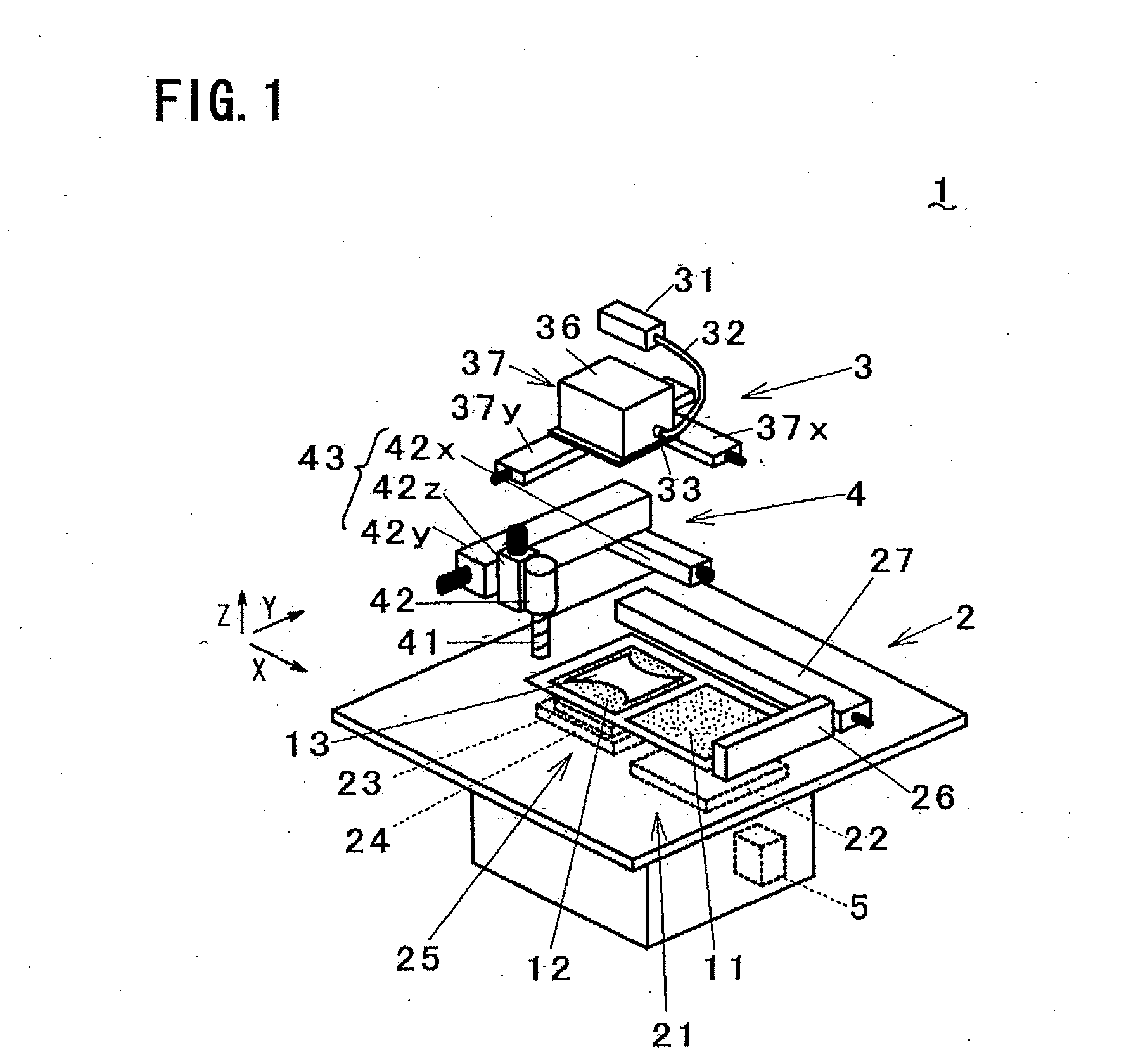
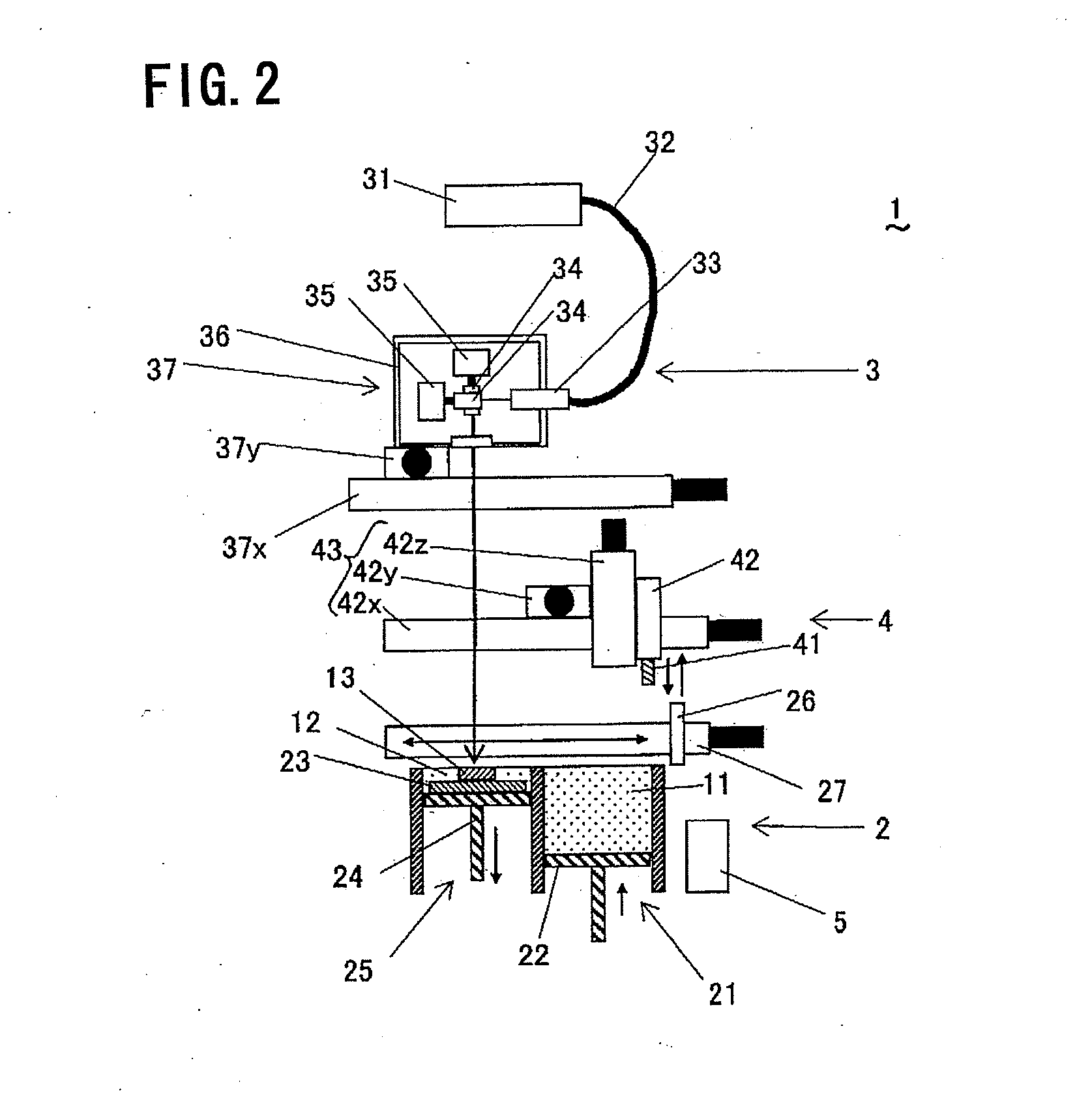
[0022]Referring to FIG. 1 to FIG. 4, manufacturing equipment for a metal powder sintered component (hereinafter, referred to as manufacturing equipment) according to a first embodiment of the present invention is described. In FIG. 1 to FIG. 3, the manufacturing equipment 1 comprises a powder layer forming portion (powder layer forming means) 2 that supplies metal powder 11 and forms a powder layer 12, a light beam irradiator (light beam irradiation means) 3 that irradiates a given point on a powder layer 12, which is formed by the powder layer forming portion 2, with light beams so as to sinter the powder layer 12 and thus form a sintered layer 13, a cutter (cutting means) 4 that cuts a three-dimensionally shaped object in which sintered layers 13 are integrally stacked, and a controller 5 that controls the operation of each portion. In this specification, a metal powder sintered component in process is referred to as a shaped object.
[0023]The powder layer forming portion 2 has a material tank 21 that supplies metal powder, a material table 22 that moves metal powder in the material tank 21 upward, a substrate 23 on which a powder layer 12 is placed, a formation table 24 that holds the substrate 23 and moves up and down, a formation tank 25 that surrounds the formation table 24, a wiper 26 that spreads the metal powder contained in the material tank 21 onto the substrate 23, and a wiper moving shaft 27 that moves the wiper 26. The light beam irradiator 3 has a light beam oscillator 31 that emits light beams, an optical fiber 32 that transmits light beams L emitted, and an optical component 33 that includes a condenser lens (not shown) and collects light beams L received from the optical fiber 32. The light beam oscillator 31 is an oscillator for e.g., carbon dioxide laser, YAG laser, or fiber laser. The light beam irradiator 3 further comprises two rotatable scan mirrors 34 that reflect light beams L from the optical component 33, and a scanner 35 that controls the rotation angles of the scan mirrors 34. The controller 5 adjusts the rotation angles of the scan mirrors 34 via the scanner 35 to direct light beams L over a powder layer 12 for scanning. The optical component 33, the scan mirrors 34, and the scanner 35 are covered by an optical cover 36 and make up a scan head 37 together with the optical cover 36.
[0024]The scan head 37 moves in a direction parallel to the surface irradiated with light beams by a scan head X shaft 37x, which is parallel to the irradiated surface and moves in the X direction, and a scan head Y shaft 37y, which is parallel to the irradiated surface and moves in the Y direction. The cutter 4 comprises a cutting tool 41 that cuts a shaped object and a milling head 42 that rotates and holds the cutting tool 41. The milling head 42 is fixed on a milling head Z shaft 42z, and moves in a direction normal to and in a direction parallel to the surface irradiated with light beams by the milling head Z shaft 42z, a milling head X shaft 42x, and a milling head Y shaft 42y. The milling head Z shaft 42z, the milling head X shaft 42x, and the milling head Y shaft 42y make up a milling head moving portion (milling head moving means) 43. The surface irradiated with light beams is covered by a chamber (not shown), which is filled with inert gas such as nitrogen gas so as to prevent oxidation of metal powder. The supply of inert gas is controlled by measuring the level of oxygen or the like within the chamber.
[0025]The operation of the manufacturing equipment 1 configured as described above is described. FIGS. 4A to 4D show the operation in sequence. First, the formation table 24 is moved down so that the difference in level between the top face of the substrate 23 and the top face of the formation tank 25 reaches Δt in length, and the metal powder 11 on the material table 22 is supplied onto the substrate 23 by the wiper 26 so as to form a powder layer 12 (FIG. 4A).
[0026]Subsequently, the scan head 37 rotates the scan mirrors to direct light beams L over an area of the powder layer 12 for scanning so that the powder layer 12 is melted to form a sintered layer 13 (FIG. 4B). The scan head 37 then moves to another area of the powder layer 12 by the scan head X shaft and the scan head Y shaft, and irradiates the area with light beams L to form the sintered layer 13 (FIG. 4C). Subsequently, the scan head 37 repeats the operation of FIGS. 4A to 4C so as to repeatedly form powder layers 12 and sintered layers 13, so that the sintered layers 13 are stacked. When sintered layers 13 reach a given thickness, the surface layer of a surface part and an unwanted part of the shaped object are cut by the cutting tool 41 of the milling head 42 (FIG. 4D). This process is repeated to manufacture a metal powder sintered component.
[0027]According to the manufacturing equipment 1, since the scan head 37 can be moved in a direction parallel to the irradiated surface, a large area can be scanned while a short distance is maintained between the scan head 37 and the irradiated surface. Thus, a large metal powder sintered component can be manufactured. The short distance between the scan head 37 and the irradiated surface can prevent a reduction in the accuracy of light beam L scanning, thus enhancing the dimensional accuracy of a shaped object. Since the dimensional accuracy of a shaped object is high, the amount of cutting by the cutting tool 41 can be reduced so that the cutting time can be reduced to shorten the machining time.

Example

Second Embodiment
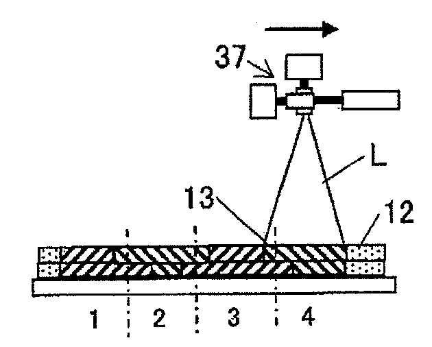
[0028]Referring to FIG. 5 to FIG. 10, a second embodiment of the present invention is described. In manufacturing equipment 1 according to this embodiment, a scan head 37 moves not in a direction parallel to the irradiated surface but in a direction normal thereto, unlike the first embodiment. Components like those in the above described embodiment are denoted by like numerals in the drawings and will not be further explained (the same shall apply hereinafter). In FIG. 5 to FIG. 7, the scan head 37 moves in a direction normal to the surface irradiated with light beams by a scan head 37z.
[0029]The operation of the manufacturing equipment 1 configured as described above is described. FIGS. 8A to 8C show the operation in sequence. First, like FIG. 4A in the first embodiment, a powder layer 12 is formed on a substrate 23 (FIG. 8A).
[0030]Subsequently, the scan head 37 rotates scan mirrors to direct light beams L over the powder layer 12 for scanning so that the powder layer 12 is melted to form a sintered layer 13 (FIG. 8B). The scan head 37 then repeats the operation of FIGS. 8A and 8B so as to repeatedly form powder layers 12 and sintered layers 13, so that the sintered layers 13 are stacked. When sintered layers 13 reach a given thickness, the surface layer of a surface part and an unwanted part of the shaped object are cut by a cutting tool 41 of a milling head 42 (FIG. 8C). This process is repeated to manufacture a metal powder sintered component.
[0031]FIGS. 9A and 9B show the relationship between the irradiation height H of the scan head 37 and the accuracy of light beam L scanning. FIG. 9A shows a case where the irradiation height H of the scan head 37 is large while FIG. 9B shows a case where the irradiation height H is small. If a light beam L directed from the scan head 37 is deviated by the same angle θ, the larger irradiation height H results in a lower accuracy of light beam L scanning because the amplitude of the light beam L is larger.
[0032]By varying the irradiation height of the scan head 37 in this manner, the accuracy of light beam L scanning can be varied. If scanning with a high degree of accuracy is needed, the irradiation height H of the scan head 37 is set small. If high scanning accuracy is not needed, the irradiation height H of the scan head 37 is set large for irradiation with light beams L.
[0033]FIGS. 10A to 10C show the relationship between the irradiation height H of the scan head 37 and the diameter D of focused light beams L. FIG. 10A shows the diameter D of focused light beams in the case where the irradiation height H of the scan head 37 is larger than average, FIG. 10B shows the diameter D of focused light beams in the case where the irradiation height H is average, and FIG. 10C shows the diameter D of focused light beams in the case where the irradiation height H is smaller than average. When the irradiation height H is larger than average, the diameter D of focused light beams is larger than that in the case where the irradiation height H is average. When the irradiation height H is smaller than average, the diameter D of focused light beams is smaller than that in the case where the irradiation height H is average. The diameter D of focused light beams can be easily controlled by changing the irradiation height H while maintaining the condenser lens and the like in the same condition. In this manner, the accuracy of light beam L scanning and the diameter of focused light beams can be easily controlled by varying the irradiation height H according to the needs of a shaped object. Thus, the machining time can be reduced.

Example

Third Embodiment
[0034]Referring to FIG. 11, a third embodiment of the present invention is described. In manufacturing equipment 1 according to this embodiment shown in FIG. 11, a scan head 37 moves in a direction parallel to and in a direction normal to the irradiated surface. A scan head Z shaft 37z is connected to a scan head Y shaft 37y, and the scan head 37 is held on the scan head Z shaft 37z. With this configuration, since the scan head 37 can move not only in a direction parallel to the irradiated surface but also in a direction normal to the irradiated surface, effects similar to those of the above described first and second embodiments can be achieved.

PUM

PropertyMeasurementUnit
Diameter
Area
tensileMPa
Particle sizePa
strength10

Description & Claims & Application Information

We can also present the details of the Description, Claims and Application information to help users get a comprehensive understanding of the technical details of the patent, such as background art, summary of invention, brief description of drawings, description of embodiments, and other original content. On the other hand, users can also determine the specific scope of protection of the technology through the list of claims; as well as understand the changes in the life cycle of the technology with the presentation of the patent timeline. Login to view more.

Similar technology patents

Liftable street lamp

InactiveCN107702044ALess attractiveLarge irradiation areaMechanical apparatusLighting support devicesEngineeringSolar cell
Owner:汪杰峰

Quincunx electrodeless lamp

InactiveCN103123049AEfficient use ofLarge irradiation areaElectric lightingLight fasteningsEngineeringLight reflection
Owner:窦敏江

Lens and lamp with lens

PendingCN112283603ALarge irradiation areaUniform light effectElongate light sourcesElectric lightingFirst lightOptical axis
Owner:SELF ELECTRONICS CO LTD

Classification and recommendation of technical efficacy words

  • Large irradiation area
  • High accuracy

Radar measurement and control precision seeder

ActiveCN103766048AHigh degree of automationLarge irradiation areaFertiliser and seeding apparatusSingle grain seedersPhysicsFertilizer
Owner:北京德邦大为科技股份有限公司

Solar-powered curtain wall roof device

PendingCN109347420ALarge irradiation areaImprove electricity production efficiencyPhotovoltaic supportsRoof covering using slabs/sheetsEngineeringSunlight
Owner:江苏广源幕墙装饰工程有限公司

light box

Owner:RISHANG OPTOELECTRONICS
Why Eureka
Try Eureka