Check valve turbine

a technology of check valve and turbine, which is applied in the direction of wind motors with perpendicular air flow, position fixation, navigation instruments, etc., can solve the problems of low center of gravity of the system, achieve low cost of manufacture, and save significant amounts of precious energy

Inactive Publication Date: 2010-09-16
ERSOY SEYHAN
View PDF22 Cites 71 Cited by
  • Summary
  • Abstract
  • Description
  • Claims
  • Application Information

AI Technical Summary

Benefits of technology

[0030]A marine check-valve turbine, i.e., a VAWT-type turbine, as disclosed herein, may be used with boats and other marine systems, as well as other wind powered vehicles or systems, to solve the problems associated with current technology. First, any heavy power producing components of the check-valve turbine may be positioned below or close to sea or ground level, which may lower a center of gravity of the system. The marine check-valve turbine disclosed herein is omni directional, and as such, is not affected by a change in a direction of the wind or a heading direction of the boat. A sail of the inventive marine check-valve turbine may be used as a regular sail to propel the boat, i.e., to push the boat when the wind direction is blowing from behind (stern direction) the turbine, without the need to strictly generate electricity, thereby saving significant amounts of precious energy needed to propel the boat. Moreover, the inventive marine check-valve turbine generates and stores power for future use even if the boat is not traveling, e.g., moored, in harbor, loading or unloading its cargo. The inventive marine check-valve turbine provides a preferable manner of generating and / or storing power for boats or other marine vessels, is inexpensive to manufacture and is lightweight compared to conventional technologies.

Problems solved by technology

First, any heavy power producing components of the check-valve turbine may be positioned below or close to sea or ground level, which may lower a center of gravity of the system.

Method used


Image

  • Check valve turbine
  • Check valve turbine
  • Check valve turbine

Examples


Embodiment Construction

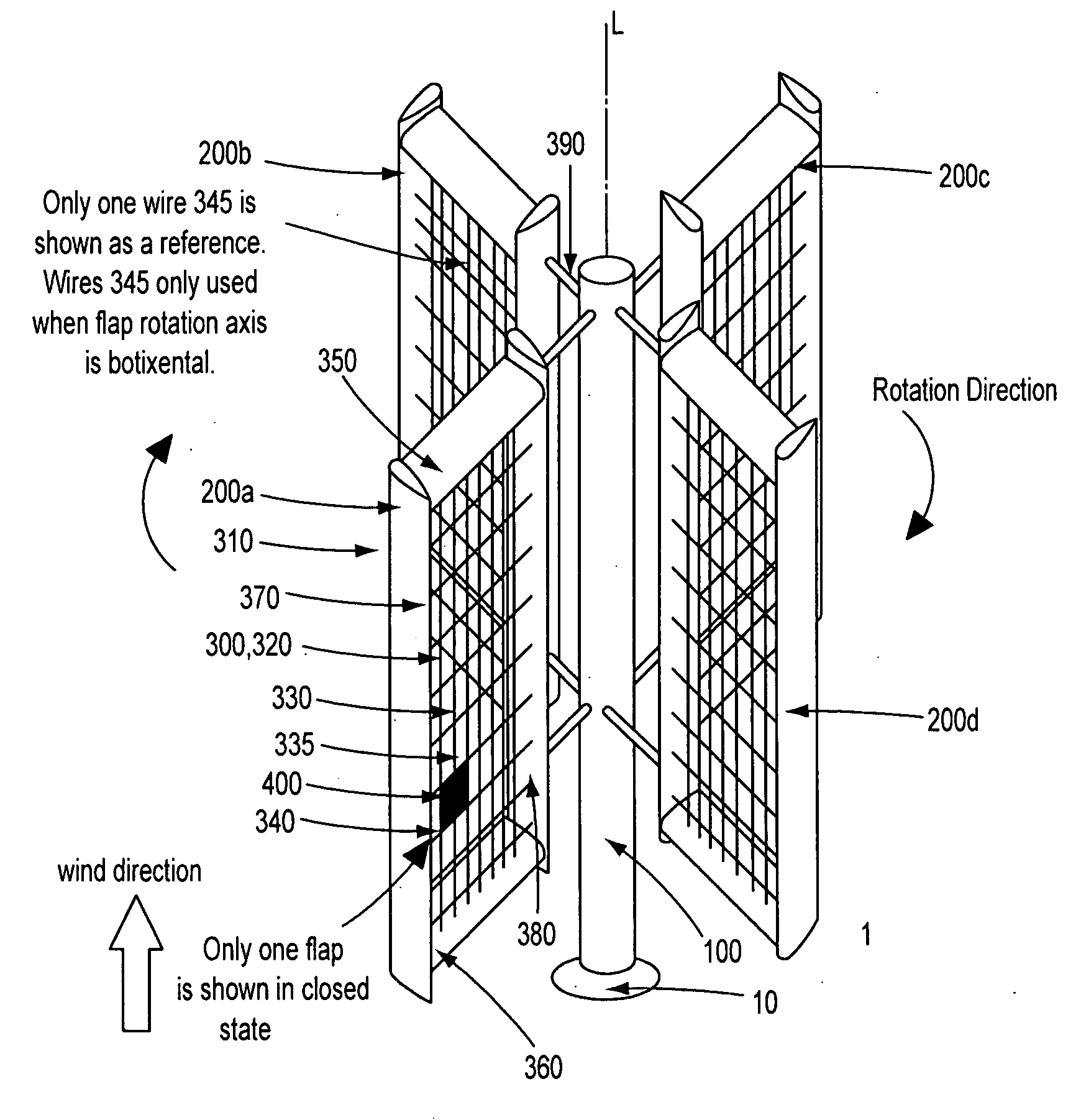
[0099]In this application, positive and negative faces of a sails and a sub-sail are mentioned. By positive face, it is meant that the wind hits the sail or the sub-sail in a direction perpendicular to a sail surface, wherein the flaps are in a CLOSED position in that face. On the other hand, by negative face it is meant that when the wind hits the sail or the sub-sail in a direction perpendicular to the sail surface, the flaps are in an OPEN position in that face. Furthermore, a positive motion of the sail, for example, is used to indicate the sail is moving in a same direction with the direction of the wind. A negative motion of the sail means that the sail is moving against the wind direction. For example, by these conventions, when the sail is undergoing the positive motion, wind is acting on the positive face of the sail. On the other hand, when the sail is undergoing the negative motion, wind is acting on the negative face. Since the marine check-valve turbine described herein...


PUM


Abstract

Aspects of an embodiment of a check valve turbine assembly include a rotation platform having an axis of rotation, a vertical member concentrically secured to the rotation platform about the axis of rotation, a rotatable sail assembly attached to the vertical member that includes a frame, a hinge beam, and a rotatable sub-sail assembly. The sub-sail assembly includes a stem beam, a sub-sail grid frame attached to the stem beam, and a plurality of flaps rotatably attached to the sub-sail grid frame and configured to move between a closed position and an open position relative to the sub frame. Aspects of a marine check valve turbine include a free-floating platform structure configured with an upper surface at or near a water surface and a vertical member secured to the platform structure about an axis of rotation and configured to extend from the upper surface of the platform structure.

Description

CROSS-REFERENCE TO RELATED APPLICATION[0001]This application is related to U.S. Non-Provisional patent application Ser. No. 12 / 331,947, titled CHECK VALVE TURBINE, filed Dec. 12, 2008, the entirety of which is hereby incorporated by reference herein.BACKGROUND OF THE INVENTION[0002]Rising fuel prices and increased awareness of global warming has placed increased emphasis on the use of renewable resources to produce energy to answer the ever increasing demand for energy. One of the earliest energy sources used by humans was wind to power sail boats and windmills. However, cheap fossil fuels rendered sail boats obsolete for commercial applications. These days sail boats are used primarily for leisure purposes only.[0003]Ancient Greeks and Romans carried cargo on the Mediterranean Sea more than 2000 years ago by using the power of the wind. It is ironic that one of the first renewable uses of the wind is the least used commercially today. There are megawatt wind turbines to power thous...

Claims


Application Information

Patent Timeline
Patent Type & Authority Applications(United States)
IPC IPC(8): B63H13/00G01C21/00F03D3/06F03D9/00
CPCB63H9/02F03D3/005F03D3/061Y02T70/58Y02B10/30Y02B10/70Y02E10/74F05B2240/93Y02T70/5236
Inventor ERSOY, SEYHAN
Owner ERSOY SEYHAN
Why Eureka
Try Eureka